Infusion set flow rate controller

A technology of a flow rate control device and an infusion set, which is applied to flow monitors, hypodermic injection devices, devices introduced into the body, etc., can solve the problems of complex structure, high price, and increased burden on patients, and achieve simple overall structure and low manufacturing cost , the effect of high accuracy

Inactive Publication Date: 2011-10-19
闫云涛
View PDF3 Cites 19 Cited by
  • Summary
  • Abstract
  • Description
  • Claims
  • Application Information

AI Technical Summary

Problems solved by technology

In order to keep the same amount of liquid medicine in the squeezed section during each extrusion push, the infusion set hose must have good elasticity. This technical defect makes this type of infusion flow rate control device need to be equipped with better elasticity and higher price. On the one hand, this increases the patient's burden, and on the other hand, it also limits the scope of use of the infusion flow rate control device; secondly, the existing intelligent infusion flow rate control device has a complex structure and high price, which limits its application. scope

Method used


Image

  • Infusion set flow rate controller
  • Infusion set flow rate controller
  • Infusion set flow rate controller

Examples


Embodiment 1

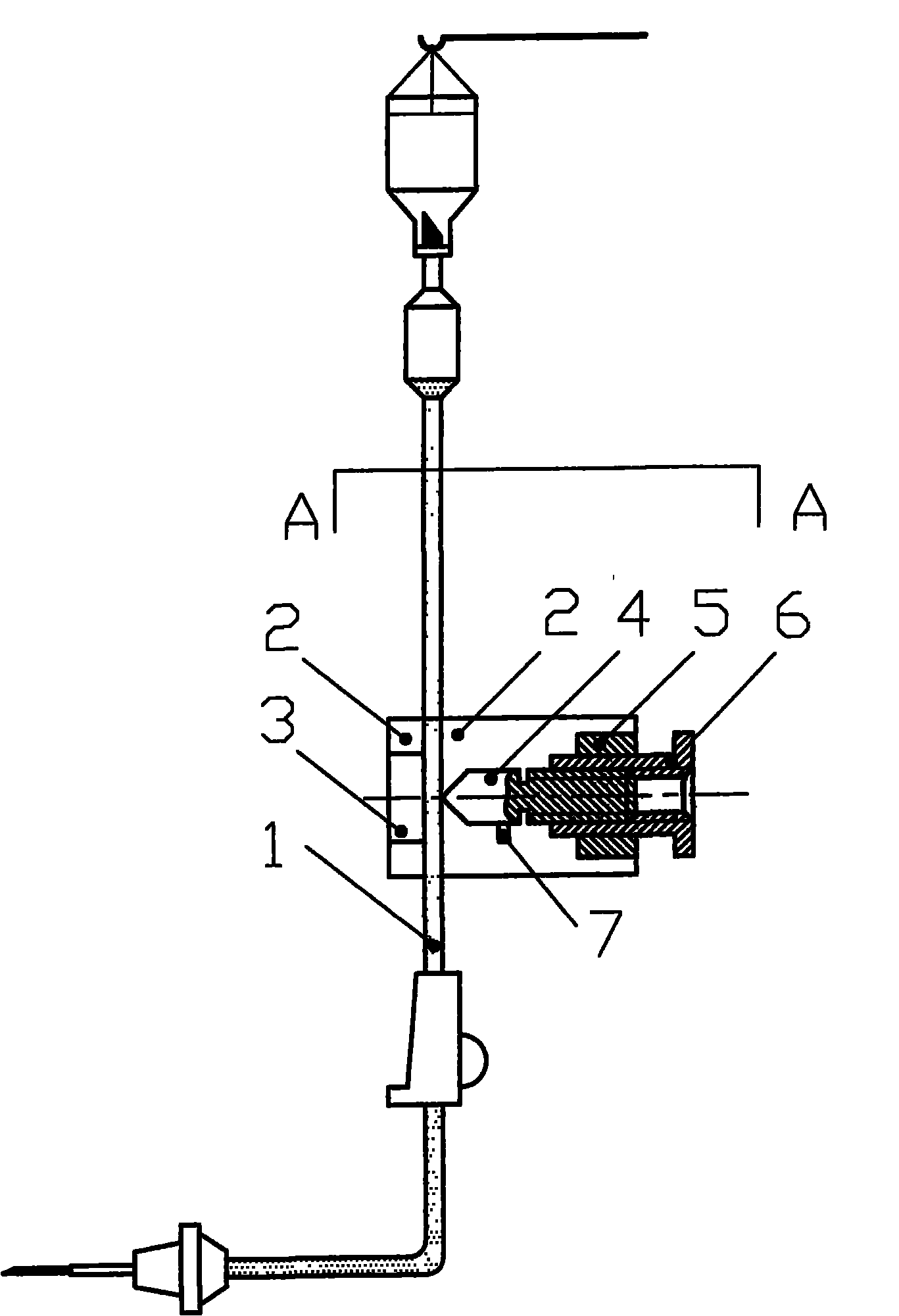
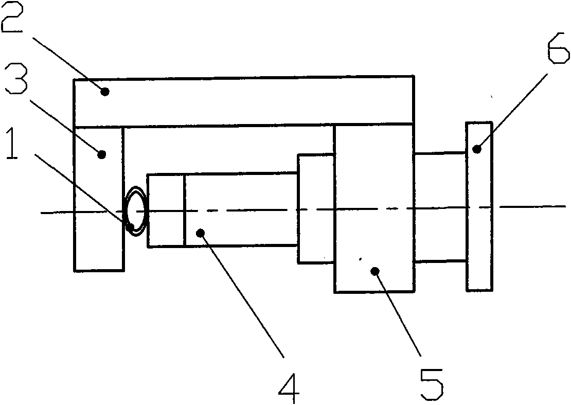
[0026] As attached figure 1 , figure 2 As shown, a flow rate control device for an infusion set includes a housing 2, a pressure-bearing plate 3, an extruder 4, a threaded frame 5, and a threaded push rod 6. The pressure-bearing plate 3 and the screw frame 5 are fixedly installed on the housing 2. The threaded frame 5 has a shaft hole, the threaded push rod 6 is assembled in the shaft hole of the threaded frame 5 and can rotate, the threaded push rod 6 has an internal threaded hole, and the front end is provided with an extruder 4, which has threads It is screwed into the threaded hole of the threaded push rod 6. A positioning device 7 is provided on the housing 2 to prevent the squeezer 4 from rotating. When in use, the infusion tube 1 is placed between the pressure-bearing plate 3 and the squeezer 4. Rotate the threaded push rod 6, under the action of the thread, the extruder 4 moves axially along the threaded push rod 6, and the distance between the extruder 4 and the pr...

Embodiment 2

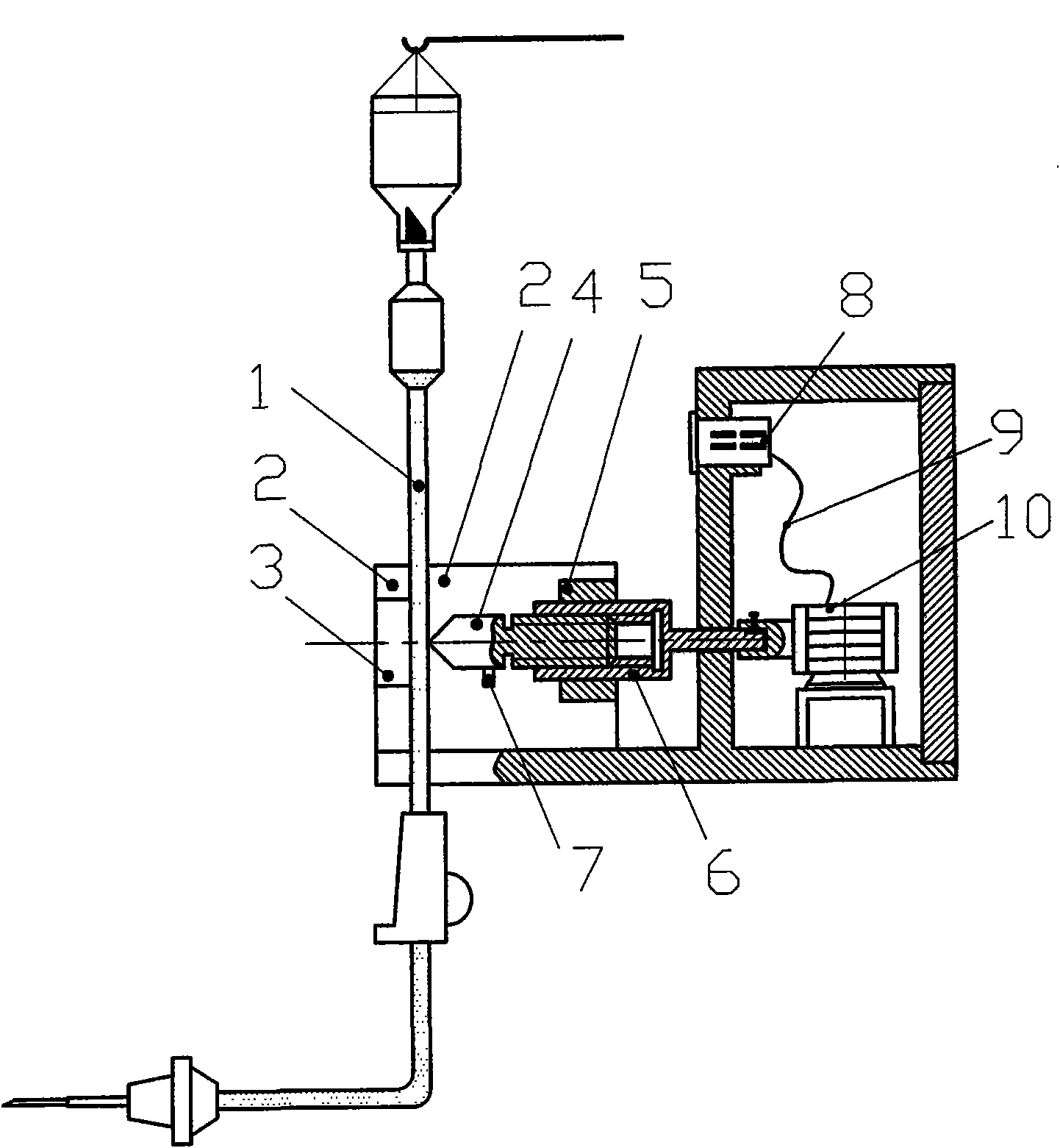
[0030] As attached image 3 As shown, a flow rate control device for an infusion set includes a housing 2, a pressure-bearing plate 3, an extruder 4, a threaded frame 5, and a threaded push rod 6. The pressure-bearing plate 3 and the screw frame 5 are fixedly installed on the housing 2. The threaded frame 5 has a shaft hole, the threaded push rod 6 is assembled in the shaft hole of the threaded frame 5 and can rotate, the threaded push rod 6 has an internal threaded hole, and the front end is provided with an extruder 4, which has threads Screwed into the threaded hole of the threaded push rod 6, the rear end of the threaded push rod 6 is connected to the motor 10, and the motor 10 is connected to the meter 8 through the wire 9, and the meter 8 and the motor 10 are both fixed on the housing 2. In order to prevent the extruder 4 from rotating, a positioning device 7 is also provided on the housing 2 to prevent the extruder 4 from rotating. The rotation angle of the threaded pus...

Embodiment 3

[0033] As attached Figure 4 As shown, a flow rate control device for an infusion set includes a housing 2, a pressure-bearing plate 3, an extruder 4, a threaded frame 5, and a threaded push rod 6. The pressure-bearing plate 3 and the screw frame 5 are fixedly installed on the housing 2. The threaded frame 5 is provided with a threaded hole, and the threaded push rod 6 has an external thread and is assembled in the threaded hole of the threaded frame 5. The front end of the threaded push rod 6 is provided with an extruder 4, and the extruder 4 and the threaded push rod 6 are arranged oppositely. In order to prevent the extruder 4 from rotating, a positioning device 7 is also provided on the housing 2 to prevent the extruder 4 from rotating. When in use, the threaded push rod 6 is rotated, and the threaded push rod 6 moves axially, pushing the squeezer 4 to move axially, thereby changing the distance between the squeezing device 4 and the pressure plate 3, and realizing the flo...


PUM


Abstract

The invention discloses an infusion set flow rate controller, belonging to the technical field of auxiliary medical appliances. The infusion set flow rate controller comprises a shell (2), a load-bearing plate (3) and a thread extrusion mechanism, wherein the load-bearing plate (3) and the thread extrusion mechanism are fixedly installed on the shell (2); and a clearance for placing an infusion set hose (1) is arranged between the load-bearing plate (3) and the thread extrusion mechanism. The distance between the thread extrusion mechanism and the load-bearing plate can be adjusted by the thread extrusion mechanism, thereby implementing control on extrusion strength of the infusion set hose. The thread extrusion mechanism can implement accurate adjustment, and thus, can implement accurate control on the flow rate of the liquor in the infusion set. In addition, the invention has the advantages of simple structure and low manufacturing cost, and is applicable to flow rate control on any existing infusion set.

Description

Technical field [0001] The invention relates to a flow rate control device for an infusion set, belonging to the technical field of auxiliary medical equipment. Background technique [0002] The speed of infusion of clinical patients should be determined according to the drug and the patient’s condition. Cancer patients, diabetic patients, the elderly, children and people with weak physical fitness need to be accurately controlled during the infusion speed and dosage. Too fast infusion may lead to poisoning. When it is more serious, it will cause edema and heart failure; if the infusion is too slow, the dose of medicine may be insufficient, which will affect the treatment and increase the unnecessary burden on patients and nursing work. For routine clinical infusion, one-time use infusion device is generally used to hang the bottle for infusion, observe with eyes, and control the speed of medicine drop by adjusting the flow regulator. For micro-infusions that require high infusi...

Claims


Application Information

Patent Timeline
Patent Type & Authority Applications(China)
IPC IPC(8): A61M5/175A61M5/172
Inventor 闫云涛
Owner 闫云涛
Why Eureka
Try Eureka