Mechanical arm modularized joint with force position perceiving function

A technology of modular joints and sensory functions, which is applied in the direction of manipulators, manufacturing tools, joints, etc., can solve the problems of restricting the application of robot systems, heavy weight of manipulators, and low integration of manipulators, and achieve light weight, small size, The effect of high integration

Inactive Publication Date: 2011-10-19
HEILONGJIANG PATENT TECH DEV
View PDF4 Cites 45 Cited by
  • Summary
  • Abstract
  • Description
  • Claims
  • Application Information

AI Technical Summary

Problems solved by technology

[0003] The present invention proposes a modular joint of a manipulator with a force-position sensing function to solve the problem of existing manipulators with heavy weigh

Method used


Image

  • Mechanical arm modularized joint with force position perceiving function
  • Mechanical arm modularized joint with force position perceiving function
  • Mechanical arm modularized joint with force position perceiving function

Examples


specific Embodiment approach 1

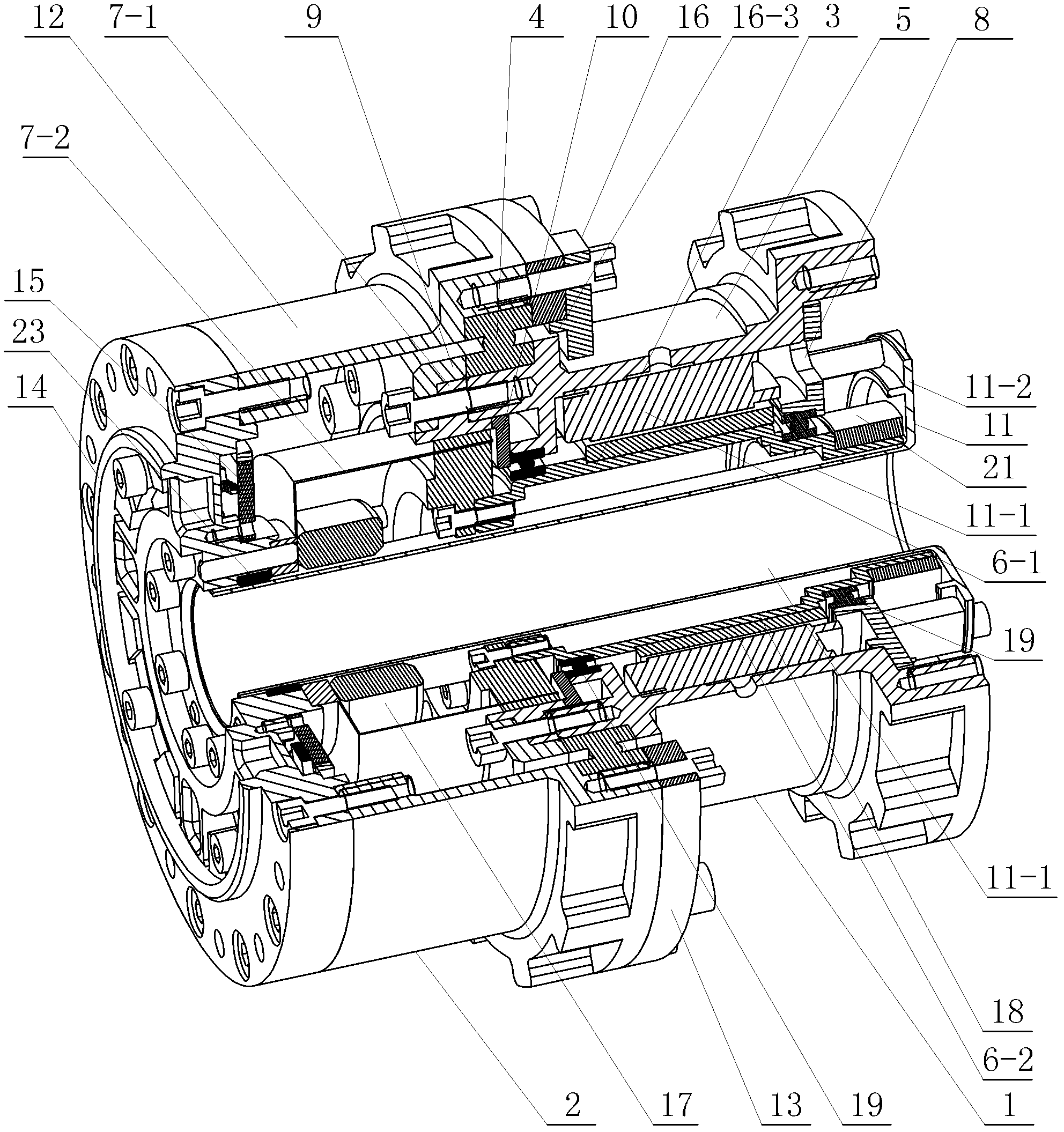
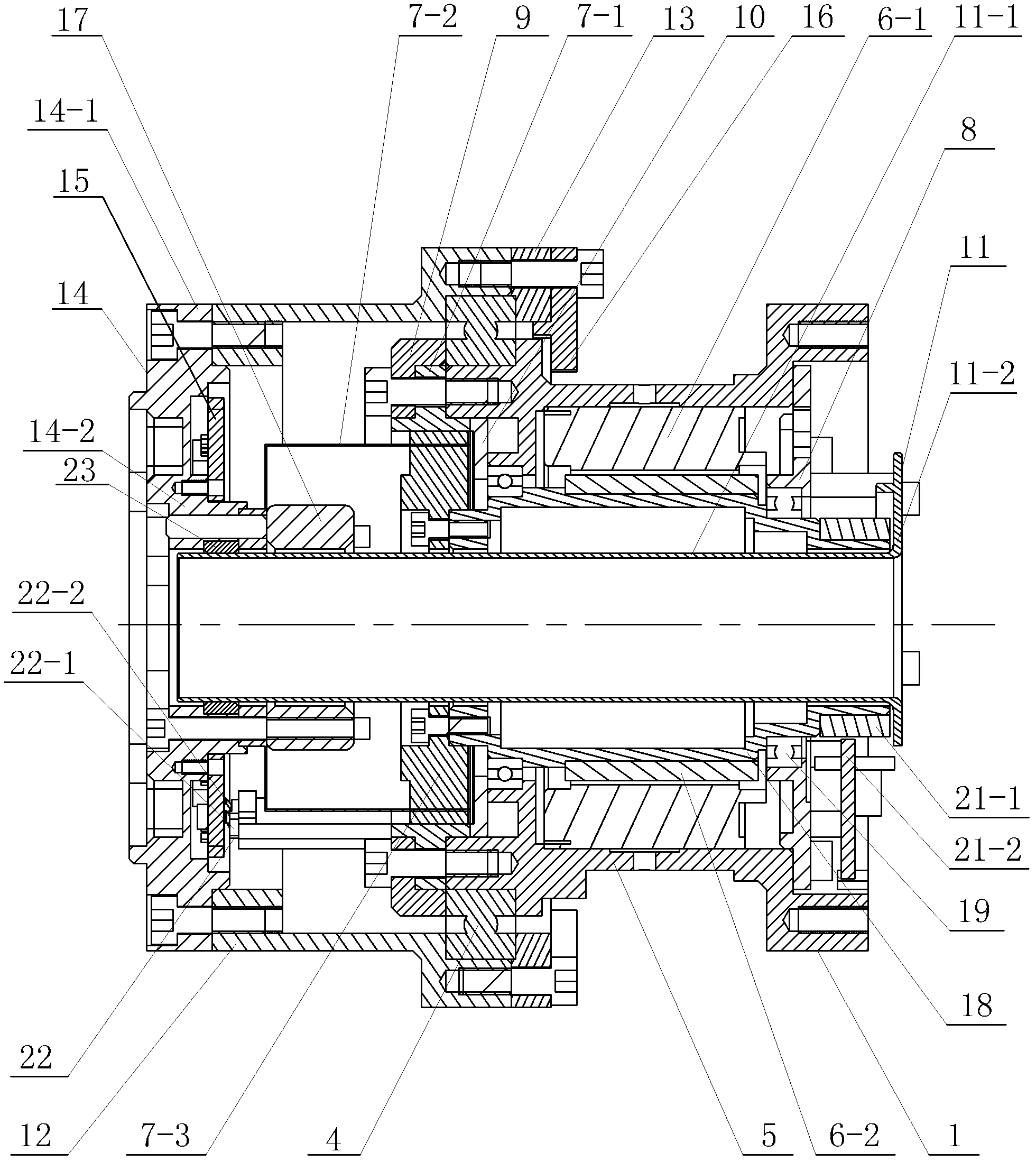
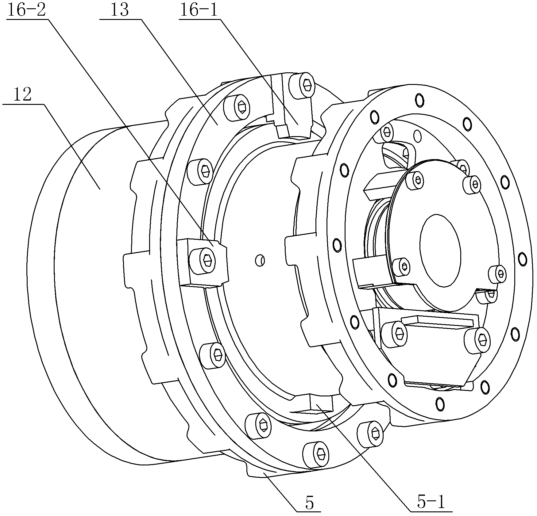
[0008] Specific implementation mode one: as Figure 1-7 As shown, the modular joint of the manipulator with force position sensing function in this embodiment includes the joint fixing device 1, the joint output device 2, the rotating device 3 and the cross roller bearing 4; the joint fixing The device 1 includes a fixed casing 5, a motor stator 6-1, a harmonic reducer rigid wheel 7-1, a first end cover 8, a second end cover 9, a pressure plate 10, a central hole wiring shaft 11, an insulating block 22-1 and The electric brush 22-2; the central hole routing shaft 11 is composed of a circular tube 11-1 and a circular plate 11-2, and one end of the circular tube 11-1 is fixedly connected with the circular plate 11-2; the joint output device 2 Including output housing 12, third end cover 13, torque sensor 14, harmonic reducer flexible wheel 7-2, connecting nut 17, nylon support 23 and two limit stops 16, two limit stops 16 Respectively the first limit block 16-1 and the second l...

specific Embodiment approach 2

[0012] Specific implementation mode two: combination figure 1 , figure 2 and Figure 5Illustrate, the torque sensor 14 of present embodiment comprises torque sensor 14 and comprises outer ring 14-1, inner ring 14-2, circuit board 15, four strain beams 14-3 and four overload protection blocks 24; Four strain beams 14 -3 is placed between the outer ring 14-1 and the inner ring 14-2, and the four strain beams 14-3 are evenly arranged along the circumferential direction of the outer ring 14-1 for transmitting the joint output torque (the torque direction is along the joint axis), an overload protection block 24 is arranged between two adjacent strain beams 14-3, four overload protection blocks 24 are connected to the inner ring 14-2, and each overload protection block 24 is connected to the outer ring 14-1 A gap is left (to make the strain beam 14-3 work within the elastic strain range, avoiding damage to the strain beam 14-3 due to output torque overload or impact), and the ci...


PUM


Abstract

The invention discloses a mechanical arm modularized joint with force position perceiving function and relates to a mechanical arm modularized joint, which aims at solving the problems of large size, large power consumption and low integrated level of the current mechanical arm. A motor stator is fixedly mounted on a fixed shell; a second end cover is mounted in an output shell; the rigid wheel of a harmonic reducer is arranged in the second end cover; the second end cover is connected with the rigid wheel of the harmonic reducer and the fixed shell; a central hole wiring shaft is arranged inthe motor stator and the rigid wheel of the harmonic reducer; a cross roller bearing is mounted between the output shell and the fixed shell; the output shell is connected with the outer ring of a torque transducer; the flexible wheel of the harmonic reducer is mounted between the inner ring of the torque transducer and a connecting nut; a third end cover is mounted on the output shell; a limit stop is mounted on the third end cover; a rotating shaft is fixedly mounted in a motor rotor; a rotating magnetic ring opposite to a position transducer is fixedly sheathed on the rotating shaft; and the generator of the harmonic reducer is connected with the rotating shaft. The mechanical arm modularized joint with the force position perceiving function is used for forming multi-free mechanical arms with light weight through series connection.

Description

technical field [0001] The invention relates to a modular joint of a mechanical arm. Background technique [0002] The robot arm is an important tool for the robot system to realize large-scale macro operations, and has an important impact on the operation ability and operation level of the robot system. Especially in recent years, the rapid development of service robots and special operation robots has put forward higher requirements for the operation arm. At present, mature robotic arms on the market have problems such as large weight, large volume, high power consumption, and low integration, which limit the application of robotic arms and the integration with robot systems. Contents of the invention [0003] The present invention proposes a modular joint of a manipulator with a force-position sensing function to solve the problem of existing manipulators with heavy weight, large volume, high power consumption, and low integration, which limit the application of the ma...

Claims


Application Information

Patent Timeline
IPC IPC(8): B25J17/00
Inventor 刘伊威谢宗武张奇刘宏
Owner HEILONGJIANG PATENT TECH DEV
Why Eureka
Try Eureka