Back contact type solar cell module
A solar cell, back contact technology, applied in circuits, electrical components, photovoltaic power generation, etc., can solve problems such as dimensional accuracy deterioration, module warpage, thermal aging, etc.
- Summary
- Abstract
- Description
- Claims
- Application Information
AI Technical Summary
Problems solved by technology
Method used
Image
Examples
Embodiment 1
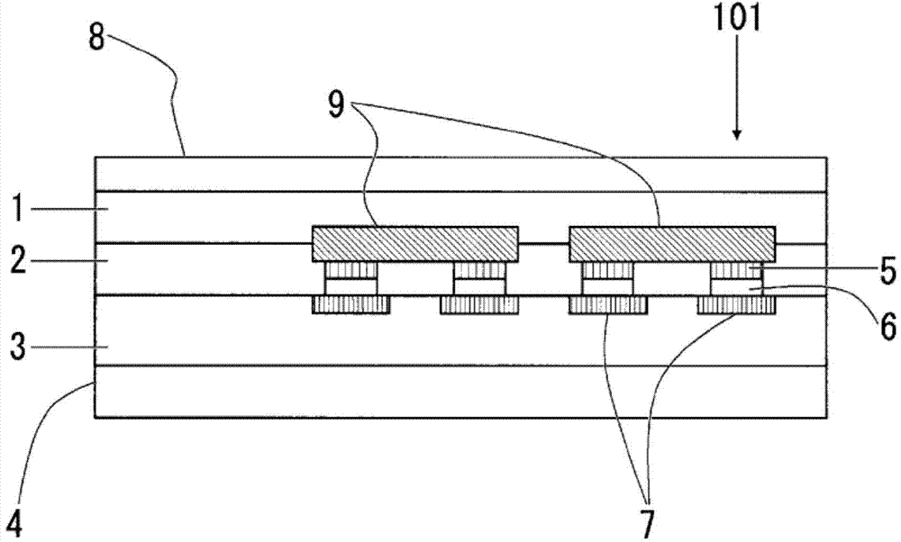
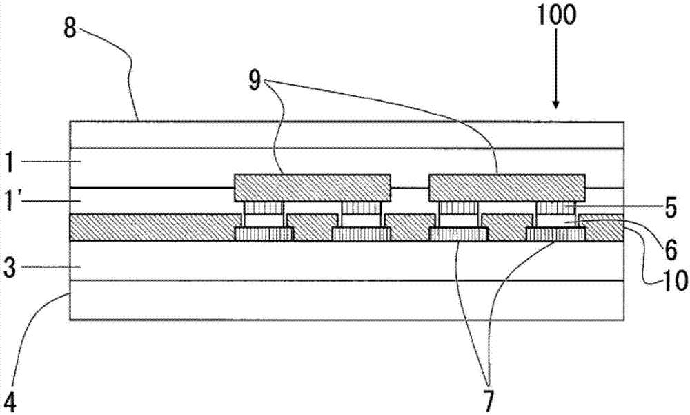
[0108] First, as Example 1, the PVF film "PV2111" (25 μm) manufactured by DuPont was used as the back sheet 4, and the general PET film "S10" (250 μm) manufactured by Toray was used as the substrate 3. The base film and electrolytic copper foil (35 μm) are used as the metal foil for forming the wiring pattern 7 so that the adhesive is dried to form a 5 g / m 2 In order to form a thick adhesive layer, use the two-component curing type polyurethane adhesive "A511 / A50" manufactured by Mitsui Chemicals to bond by dry lamination.
[0109] Furthermore, patterning was performed by etching on the upper surface of the electrolytic copper foil to form a circuit-attached backplane having a wiring pattern 7 .
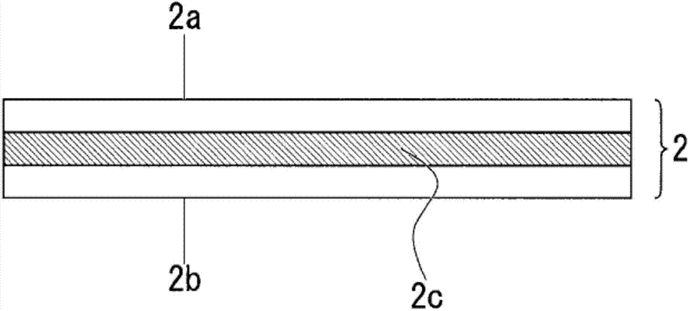
[0110] In addition to the back sheet with the circuit, EVA-based sealing material "EF1001" manufactured by Toppan Printing Co. 75 μm was extruded to prepare a sealing material 2 “EVA sealing material (75 μm) / transparent PET (50 μm) / EVA sealing material (75 μm)” with an insulating la...
Embodiment 2
[0116] As Example 2, except that the raw material of the sealing material 2 with an insulating layer was different, a back-contact solar cell module was produced with the same structure and the same operation method as Example 1.
[0117] As a sealing material with an insulating layer, Mitsui Chemicals primer "Takelac A3210" was applied on both sides of white PET "Teijin DuPont Films VW (50 μm)" in an amount of 1 g / m 2After the undercoat layer was formed in the same way, EMAA resin ("Nucleel N0908C" manufactured by DuPont Polychemical Co., Ltd.) was extruded through an extruder (extruder) to 50 μm, and the sealing material 2 "EMAA with an insulating layer was prepared. (50 μm) / base coat (AC) layer / white PET (50 μm) / base coat (AC) layer / EMAA (50 μm)”.
Embodiment 3
[0119] As Example 3, except that the raw material of the sealing material 2 with an insulating layer was different, a back-contact solar cell module was produced with the same structure and the same operation method as Example 1.
[0120] As a sealing material with an insulating layer, on both sides of black PET "Teijin DuPont Films VK (50μm)" so that the coating amount after drying is 5g / m 2 Two-component curing polyurethane-based dry lamination adhesive (Mitsui Chemicals "A515") was applied by the method, and after dry lamination (DL), the ionomer film "HM52" manufactured by Tamapoly Co., Ltd. (50 μm) was pasted on the dry lamination film to prepare a sealing material 2 “HM52 (50 μm) / DL / black PET (50 μm) / DL / HM52 (50 μm)” with an insulating layer.
PUM
 Abstract
Description
Claims
Application Information
 - R&D
- Intellectual Property
- Life Sciences
- Materials
- Tech Scout
- Unparalleled Data Quality
- Higher Quality Content
- 60% Fewer Hallucinations
Browse by: Latest US Patents, China's latest patents, Technical Efficacy Thesaurus, Application Domain, Technology Topic, Popular Technical Reports.
© 2025 PatSnap. All rights reserved.Legal|Privacy policy|Modern Slavery Act Transparency Statement|Sitemap|About US| Contact US: help@patsnap.com


