
Method for efficiently cooperatively sensing rotation scanning radar signals and system thereof

A scanning radar and collaborative sensing technology, applied in the information field, can solve problems such as inability to judge, generate false alarms, and long sensing time, and achieve the effects of short sensing time, strong reliability, and avoiding interference

Inactive Publication Date: 2011-10-19
SHANGHAI RES CENT FOR WIRELESS COMM
View PDF4 Cites 8 Cited by
  • Summary
  • Abstract
  • Description
  • Claims
  • Application Information

AI Technical Summary

Problems solved by technology

However, this method has the following two disadvantages: (1) the sensing device cannot determine whether the received pulse train is a radar pulse train or an interference pulse train, and false alarms may occur; (2) if the received pulse train is indeed radar signal, then within a radar scanning cycle, the sensing device still cannot judge whether the pulse train is a rotating scanning radar and obtain the corresponding parameters of the radar
If it is necessary to further determine whether the radar signal is a rotating scanning radar, it is necessary to wait for the arrival of the next scanning cycle of the radar, which will result in a long perception time to determine the existence of the radar signal and its corresponding parameters
Although the above cooperative sensing mechanism is relatively complete, its disadvantage is that the prior information of the radar system (such as the radar scanning cycle) known to the sensing device is required to determine the sensing cycle. This requirement cannot be met in practical applications, which limits the use of the sensing algorithm. Reliability and Practical Applications

Method used


Image

  • Method for efficiently cooperatively sensing rotation scanning radar signals and system thereof
  • Method for efficiently cooperatively sensing rotation scanning radar signals and system thereof
  • Method for efficiently cooperatively sensing rotation scanning radar signals and system thereof

Examples


Embodiment 1

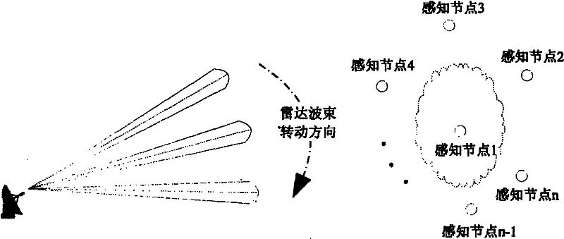
[0054] This embodiment provides a method for efficient cooperative sensing of rotating scanning radar signals, the method including the following steps:

[0055] Step 1, setting up a central processing node and several sensing nodes; the sensing node is a communication node with a sensing function and can work on multiple channels; the central processing node also has a sensing function.

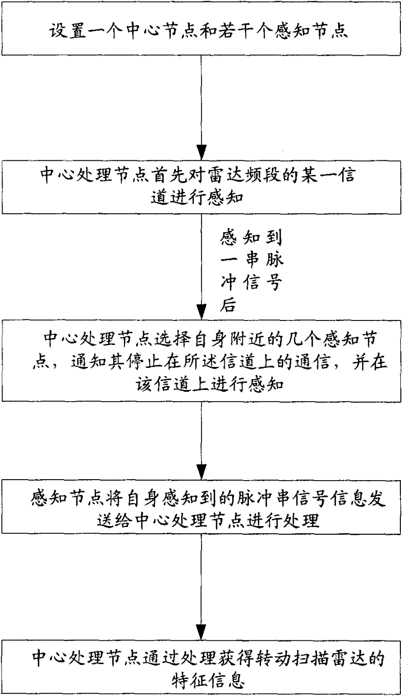
[0056] Step 2, the central processing node selects certain sensing nodes to sense a certain channel in the radar frequency band, and obtains sensing results; the sensing results include the order in which each sensing node perceives the rotating scanning radar signal and the difference in sensing time;

[0057] The central processing node first senses a certain channel in the radar frequency band, and when the central processing node perceives a series of pulse signals, it selects certain sensing nodes near the central processing node and informs the selected sensing nodes to stop communicat...

Embodiment 2

[0071]The difference between this embodiment and Embodiment 1 is that the central processing node may not have a perception function, but is a node device with information collection and processing functions; in step 2, the central processing node itself does not perform perception, but Select a sensing node to sense a channel in the radar frequency band first;

[0072] The specific perception steps are:

[0073] B1. The central processing node first selects the first sensing node to sense a certain channel in the radar frequency band. After the first sensing node perceives a series of pulse signals, it sends the characteristic information and sensing time of the pulse signals to central processing node;

[0074] B2. The central processing node re-selects several sensing nodes near the first sensing node, notifies the re-selected sensing nodes to stop communication on the channel and requires the re-selected sensing nodes to The channel is sensed, and the central processing ...

Embodiment 3

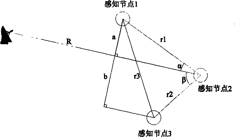
[0083] The calculation process of the method of the present invention is:

[0084] Step 1', assuming that there are N communication nodes with sensing functions working on multiple channels, the communication nodes are called sensing nodes, and the distance between each sensing node is greater than twice the coverage radius of the base station;

[0085] Step 2', the central processing node first selects the first sensing node or the central processing node to sense a certain channel in the radar frequency band, and if it senses the occurrence of a series of pulse signals, it notifies the first sensing node or the central processing node Several nearby sensing nodes stop communication on the channel and require the selected sensing node to sense the channel, and the central processing node selects at least two of the sensing results fed back by the sensing nodes Sensing results of sensing nodes.

[0086] Usually, how many sensing nodes are selected for sensing results is deter...


PUM


Abstract

The invention discloses a method for efficiently cooperatively sensing rotation scanning radar signals and a system thereof. The method includes the following steps: step 1, a center processing node and several sensing nodes are arranged; step 2, the center processing node selects some sensing nodes to sense a channel of a radar frequency band so as to obtain a sensing result; step 3, the center processing node processes the sensing result so as to obtain characteristic information of the rotation scanning radar. By using the method, the rotation scanning radar can be accurately identified; scanning direction of the rotation scanning radar can be confirmed in less than a scanning period time; corresponding parameters of the sensed radar, such as the scanning cycle, a location and the like, can be further confirmed in less than two scanning period time. Prior information is not needed to be known. Sensing time is short, efficiency is high and reliability is strong. Secondary communication system can reasonably and efficiently share the radar frequency band. Interference on radar radio determination business can be avoided.

Description

technical field [0001] The invention belongs to the field of information technology, and relates to a spectrum sensing method in a cognitive radio system in which a communication system and a radar coexist, and in particular to a method and system for efficient cooperative sensing of a rotating scanning radar signal. Background technique [0002] In recent years, with the establishment of various wireless communication system standards, the deployment of wireless communication networks, and the continuous emergence of new wireless services, the demand for wireless spectrum is increasing. Moreover, after the development of 1G (first generation wireless communication system), 2G and 3G, the wireless communication network is currently developing towards a new generation of 4G / B3G wireless communication network, which will realize seamless broadband wireless access anytime and anywhere, also known as It is an IMT-Advanced system. The new generation of 4G / B3G wireless communicat...

Claims


Application Information

Patent Timeline
IPC IPC(8): H04B17/00H04W16/14H04B17/382
Inventor 王瑞易辉跃胡宏林王力
Owner SHANGHAI RES CENT FOR WIRELESS COMM
Learn More