Method for bonding polysilicon ingot and tray
A technology of polycrystalline silicon ingots and bonding method, which is applied to fine working devices, working accessories, stone processing equipment, etc., can solve the problems of polycrystalline silicon ingots producing foam scraps and a large amount of foaming agent, and achieves less debris, reduced dosage, Avoid the effect of foam crumbs
- Summary
- Abstract
- Description
- Claims
- Application Information
AI Technical Summary
Problems solved by technology
Method used
Image

Examples
Embodiment 1
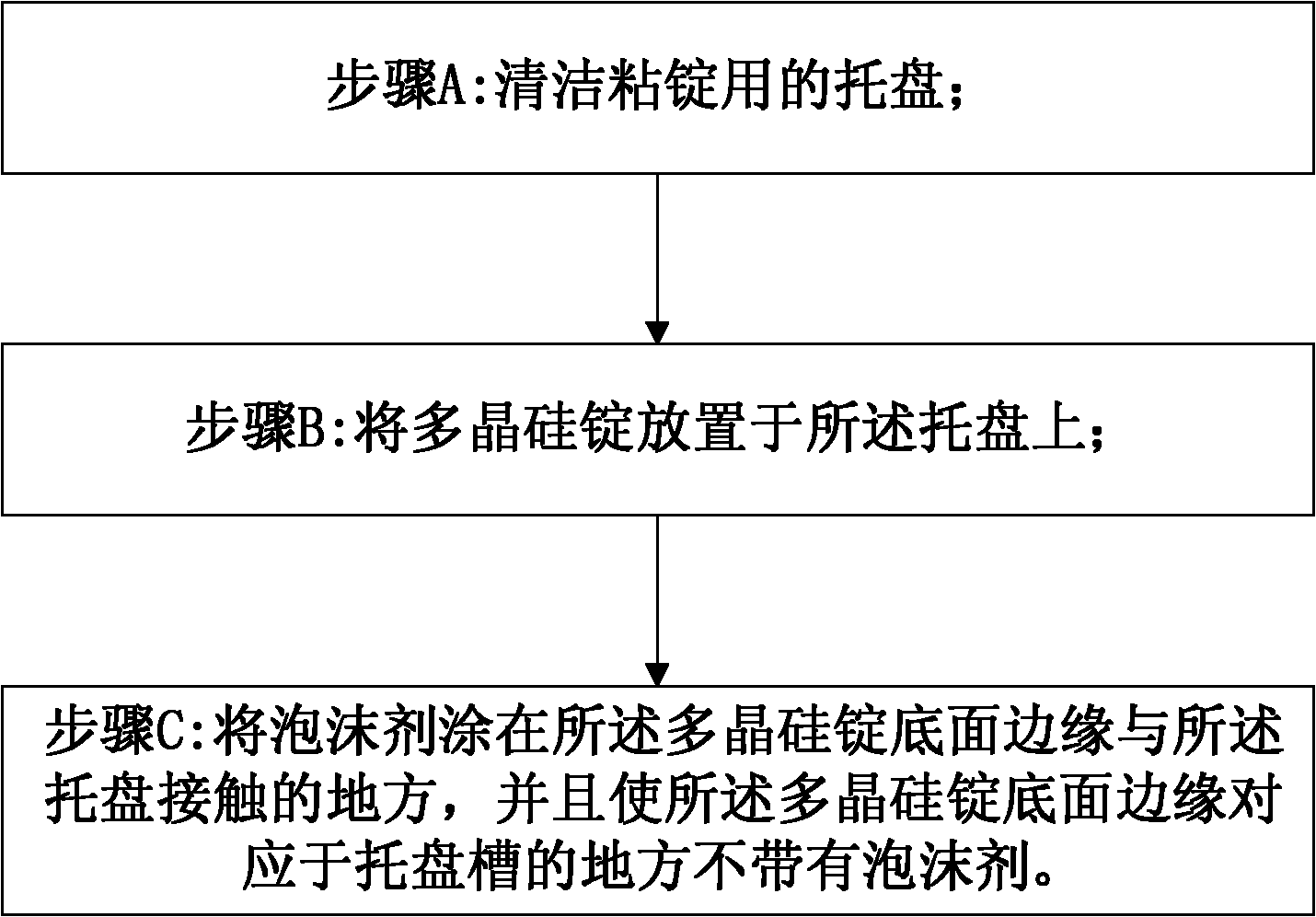
[0032] figure 2 It is a schematic flow chart of Embodiment 1 of the bonding method of the present invention. Such as figure 2 As shown, the bonding method of the polysilicon ingot and the pallet provided in Embodiment 1 includes:
[0033] Step A: Clean the tray used for sticking ingots;
[0034] Step B: placing polysilicon ingots on the tray;
[0035] Step C: Apply foam agent to the place where the edge of the bottom surface of the polycrystalline silicon ingot is in contact with the tray, and make the edge of the bottom surface of the polycrystalline silicon ingot corresponding to the groove of the tray free of foam agent.
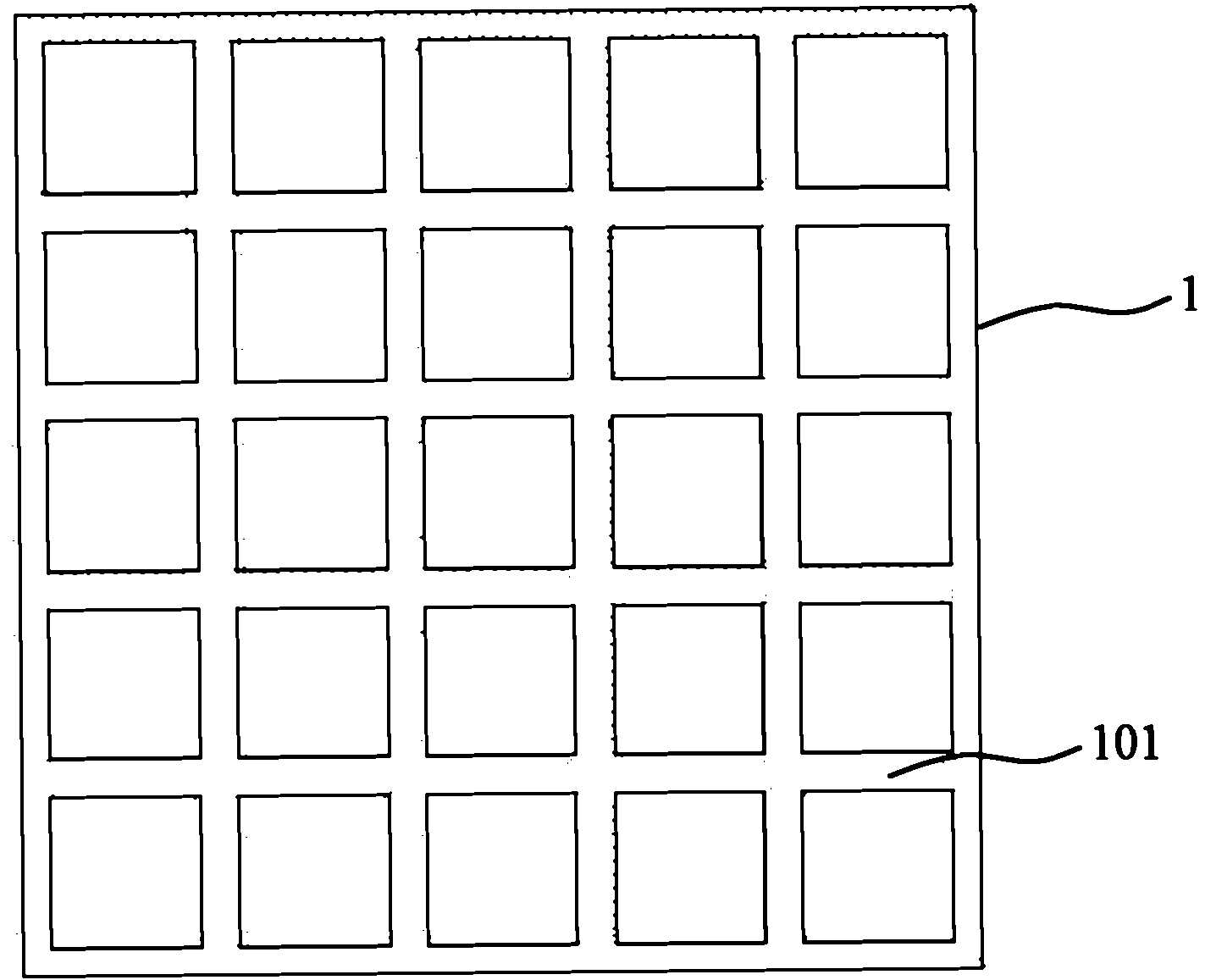
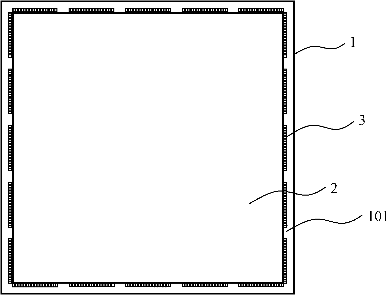
[0036] image 3 It is a schematic diagram of sticking ingots using the bonding method of Embodiment 1. Such as image 3 As shown, when using the bonding method provided in Example 1 to bond ingots, first clean the tray 1 for bonding polysilicon ingots 2; Move to the exact position; finally spray foam agent 3 on the edge of the contact surface bet...
Embodiment 2
[0039] Figure 4 It is a schematic flow chart of Embodiment 2 of the bonding method of the present invention. Such as Figure 4 As shown, the bonding method of the polysilicon ingot and the pallet provided in Embodiment 2 includes:
[0040] Step A: Clean the tray used for sticking ingots;
[0041] Step B11: apply the foam agent on the tray, and keep the tray slot free of foam agent;
[0042] Step B12: placing the polysilicon ingot on the tray coated with foam agent;
[0043] Step C: Apply foam agent to the place where the edge of the bottom surface of the polycrystalline silicon ingot is in contact with the tray, and make the edge of the bottom surface of the polycrystalline silicon ingot corresponding to the groove of the tray free of foam agent.
[0044] When using the bonding method provided in Example 2 to stick the ingot, not only the foam agent is applied to the place where the edge of the bottom surface of the polycrystalline silicon ingot is in contact with the tra...
Embodiment 3
[0046] Figure 5 It is a schematic flow chart of Embodiment 3 of the bonding method of the present invention. Such as Figure 5 As shown, the bonding method of the polysilicon ingot and the pallet provided in Embodiment 3 includes:
[0047] Step A: Clean the tray used for sticking ingots;
[0048] Step B21: laying a layer of buffer thin pad that can be completely covered by the lower surface of the polysilicon ingot on the tray;
[0049] Step B22: pressing the polysilicon ingot on the buffer pad;
[0050] Step C: Apply foam agent to the place where the edge of the bottom surface of the polycrystalline silicon ingot is in contact with the tray, and make the edge of the bottom surface of the polycrystalline silicon ingot corresponding to the groove of the tray free of foam agent.
[0051] When using the bonding method provided in this embodiment to bond ingots, first clean the tray used for bonding polysilicon ingots; then lay a layer of cushioning pad on the upper surface o...
PUM
 Abstract
Description
Claims
Application Information
 - R&D
- Intellectual Property
- Life Sciences
- Materials
- Tech Scout
- Unparalleled Data Quality
- Higher Quality Content
- 60% Fewer Hallucinations
Browse by: Latest US Patents, China's latest patents, Technical Efficacy Thesaurus, Application Domain, Technology Topic, Popular Technical Reports.
© 2025 PatSnap. All rights reserved.Legal|Privacy policy|Modern Slavery Act Transparency Statement|Sitemap|About US| Contact US: help@patsnap.com