Hydraulic vertical-type conveying device

A conveying device, vertical technology, applied in the field of hydraulic vertical conveying devices, can solve problems such as not being enough for the public to realize, and achieve the effect of a reasonable overall structure

Active Publication Date: 2012-11-07
CHANGSHU TONGRUN AUTO ACCESSORY
View PDF4 Cites 6 Cited by
  • Summary
  • Abstract
  • Description
  • Claims
  • Application Information

AI Technical Summary

Problems solved by technology

However, this patent scheme does not provide corresponding technical inspiration for the oil cylinder structure as the core component, so if the oil cylinder structure of the known vertical jack is purely applied, a series of technical problems will arise, such as the position of the oil return valve as the pressure release mechanism 1. The structure of the oil return valve itself, and the cooperation of the tread plate and the pump core of the oil cylinder, etc. all need to be reasonably designed. Not mentioned enough for public perception

Method used


Image

  • Hydraulic vertical-type conveying device
  • Hydraulic vertical-type conveying device

Examples


Embodiment Construction

[0018] In order to enable the examiners of the patent office, especially the public, to understand the technical essence and beneficial effects of the present invention more clearly, the applicant will describe in detail the following in the form of examples, but none of the descriptions of the examples is an explanation of the solutions of the present invention. Any equivalent transformation made according to the concept of the present invention which is merely formal but not substantive shall be regarded as the scope of the technical solution of the present invention.

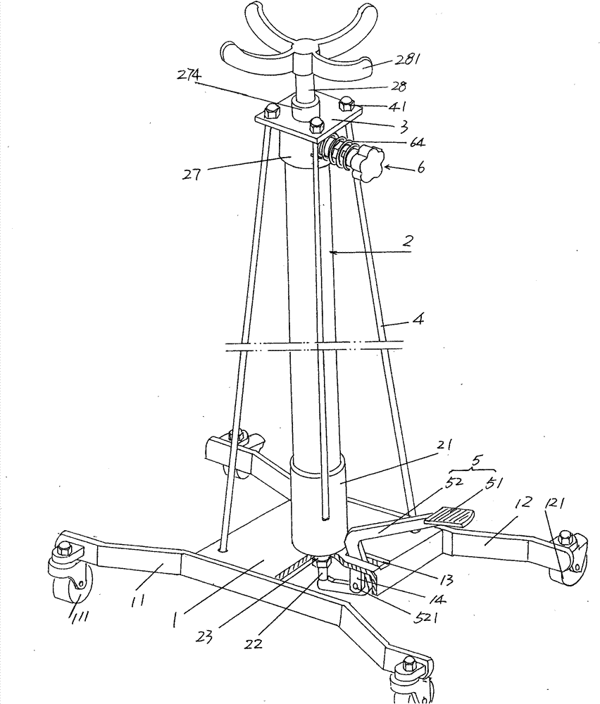
[0019] please see figure 1 , the fixed seat 1 is given, and a first roller frame 11 is fixed on one side of the lower fixed seat 1. Both ends of the first roller frame 11 extend out of the lower fixed seat 1 and each pivot is provided with a first roller 111 ; a second roller frame 12 is fixed on the other side of the lower fixing seat 1 , both ends of the second roller frame 12 protrude from the lower fixing...


PUM


Abstract

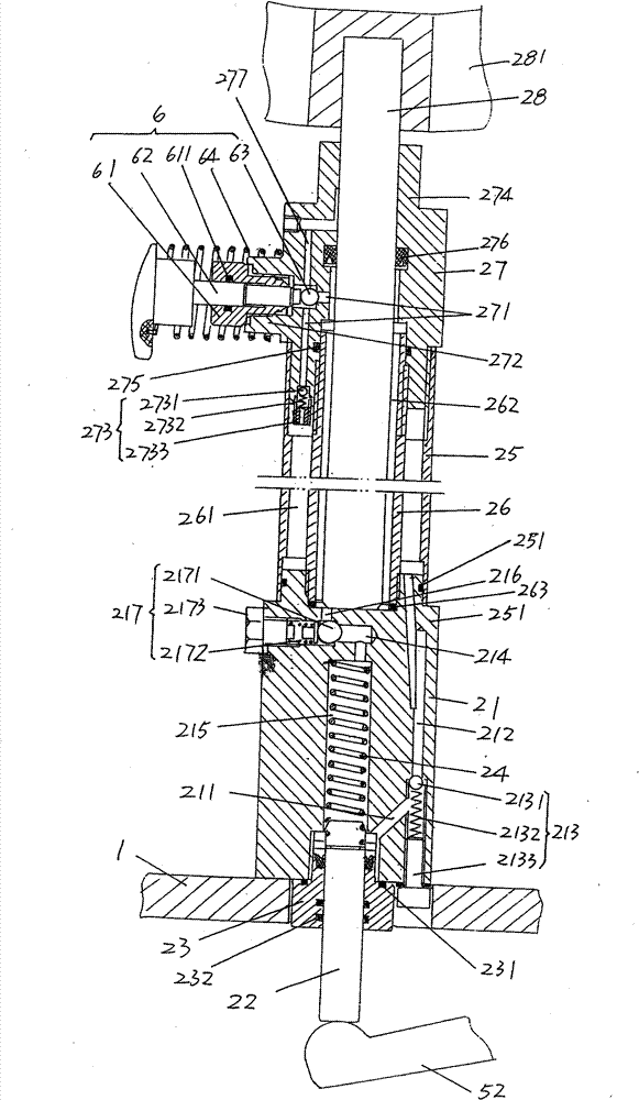
The invention discloses a hydraulic vertical-type conveying device and belongs to the technical field of conveying apparatuses. The conveying device comprises a lower fixing seat, an oil cylinder, a group of reinforcing struts, a thread-type oil pumping mechanism and a pressure oil releasing mechanism, and is characterized in that the oil cylinder comprises an oil cylinder base, a pump core, a pump cover, a pump core spring, a cylinder sleeve, an inner cylinder, a cylinder cover and a piston rod; the oil cylinder base is arranged on the lower fixing seat and is provided with an oil inlet duct, an oil return duct, a ball valve, a high-pressure oil duct, a high-pressure oil cavity, a high-pressure oil discharging duct and a high-pressure oil on-off valve; and the end part, extending out thecylinder cover, of the piston rod is fixedly provided with a bracket, a thread-type oil-pumping mechanism is matched with the pump core, the pressure releasing mechanism is arranged on the cylinder cover, and an upper fixing seat is sleeved on the cylinder cover. The hydraulic vertical-type conveying device has the advantages of rational integral structure, ideal work stability, convenience in operation and labor conservation.

Description

technical field [0001] The invention belongs to the technical field of conveying equipment, and in particular relates to a hydraulic vertical conveying device, which is applied to industries such as vehicle and mechanical equipment maintenance. Background technique [0002] The use of conveying devices is often involved in the vehicle repair industry, especially in the vehicle repair industry, and in machinery repair departments such as power plant maintenance departments of enterprises. Taking the automobile maintenance industry such as the auto repair factory as an example, after the vehicle is lifted by the lifting device or lifted by the lifting device, when disassembling parts such as gearboxes and exhaust pipes, in order not to fall damage and avoid posing a threat to the safety of maintenance personnel Therefore, it is necessary to support the disassembled gearbox, exhaust pipe, oil pan and other components by means of a transport device, and move them to the repair s...

Claims


Application Information

Patent Timeline
Patent Type & Authority Patents(China)
IPC IPC(8): B65G7/06
Inventor 石永良杜镇陈旦唐循申
Owner CHANGSHU TONGRUN AUTO ACCESSORY
Why Eureka
Try Eureka