Full optics differential monitoring device based on Pockels effect

A monitoring device and optical technology, applied in the direction of voltage/current isolation, can solve the problems of beam interference and low deflection angle accuracy, and achieve the effect of low electromagnetic interference and high accuracy

A monitoring device and optical technology, applied in the direction of voltage/current isolation, can solve the problems of beam interference and low deflection angle accuracy, and achieve the effect of low electromagnetic interference and high accuracy

CN102226818AInactive Publication Date: 2011-10-26HARBIN INST OF TECH

Image

  • Full optics differential monitoring device based on Pockels effect
  • Full optics differential monitoring device based on Pockels effect
  • Full optics differential monitoring device based on Pockels effect

Examples


specific Embodiment approach 1

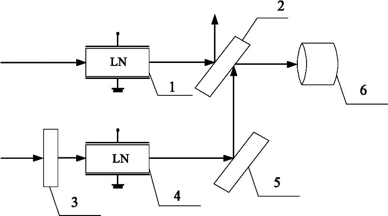
[0009] Specific implementation mode 1. Combination figure 1 Illustrate this specific embodiment, the all-optical differential monitoring device based on Pockels effect, it comprises photodetector 6, and it comprises No. 1 electro-optic crystal 1, No. 1 half mirror 2, half-wave plate 3, two No. electro-optic crystal 4 and No. one total mirror 5, the first incident light beam is transmitted through the first electro-optic crystal 2 to obtain the first polarized light beam, and the first polarized light beam is incident on the No. one half-transparent half-mirror 3, and passes through a No. half mirror 3 is divided into reflected light beam and transmitted light beam, and described reflected light beam emerges along the direction perpendicular to the optical axis of the first polarized light beam;

[0010] The second incident light beam is incident on the second electro-optic crystal 4 after being transmitted by the half-wave plate 3, and the second polarized light beam is obtain...

specific Embodiment approach 2

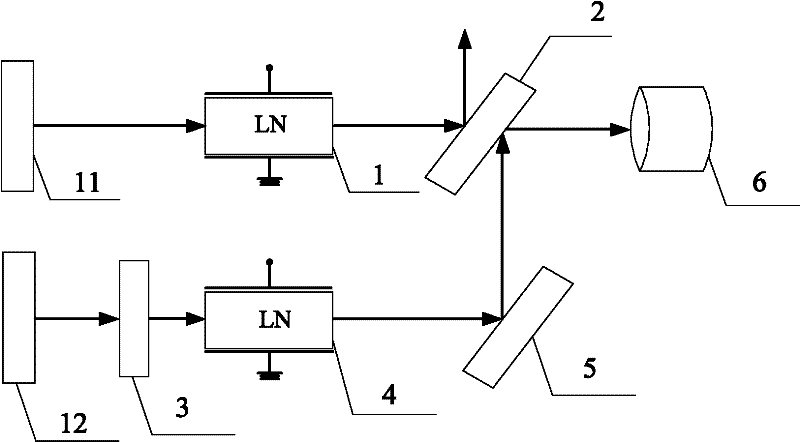
[0012] Embodiment 2. The difference between this embodiment and the all-optical differential monitoring device based on the Pockels effect described in Embodiment 1 is that it also includes No. 1 light source 11 and No. 2 light source 12. The first incident The light beam is emitted by No. 1 light source 11 , and the second incident light beam is emitted by No. 2 light source 12 .

specific Embodiment approach 3

[0013] Embodiment 3. The difference between this embodiment and the all-optical differential monitoring device based on the Pockels effect described in Embodiment 2 is that both the No. 1 light source 11 and the No. 2 light source 12 are semiconductors with a wavelength band of 850 nm. laser.


PUM


Abstract

Provided is a full optics differential monitoring device based on Pockels effects. The invention relates to the field of optics control and solves the problems that light beams are severely interfered by electromagnetic in the detection process of a present detection apparatus and the accuracy is low when digital signals are used to judge the deflection angle of lights. A first polarized light beam is obtained when a first incident light beam of the monitoring device is transmitted by a first electric light crystal. The first polarized light beam is divided into a reflected light beam and a transmitted light beam through number one semitransparent mirror. The reflected light beam emits in the direction vertical to the optical axis of the first polarized light beam. A second polarized light beam is obtained when a second incident light beam of the monitoring device is transmitted by a second electric light crystal. The second polarized light beam is reflected by a number one total reflective mirror to obtain another reflected light beam which gathers at the light input terminal of a photoelectric detector with the transmitted light beam transmitted by the number one semitransparent mirror. The invention can be widely applied to the field of light control.

Description

technical field [0001] The invention relates to the field of optical control. Background technique [0002] The existing detection instruments are all light intensity detection devices after the light beam passes through the optical voltage transformer. The light information received by the photoelectric converter in the light intensity detection device is the light information that changes after the voltage mutual induction. The two photoelectric converters Compare the received two beams of light with digital signals. If there is a difference between the two digital signals, it means that the voltage is abnormal during the transmission of light, so the light beam passing through the photoelectric converter has also changed, thereby starting the protection device. . The disadvantages of the existing technology are: the cost of using two photodetectors is high, and they are subject to strong electromagnetic interference during use, and the errors that occur after the optical...

Claims


Application Information

Patent Timeline
26 Oct 2011
Publication
CN102226818A
IPC
G01R15/24
Inventors
申岩; 郭志忠