Full-optical fiber difference stream measuring device based on faraday effect

A Faraday effect and measurement device technology, applied in the direction of voltage/current isolation, etc., can solve the problems of high cost, strong electromagnetic interference of beams, and low accuracy of deflection angle, achieving high accuracy, low electromagnetic interference, and cost reduction Effect

Inactive Publication Date: 2012-05-23
HARBIN INST OF TECH
View PDF0 Cites 0 Cited by
  • Summary
  • Abstract
  • Description
  • Claims
  • Application Information

AI Technical Summary

Problems solved by technology

[0003] In order to solve the existing problem that the light beam is subject to strong electromagnetic interference during the propagation process of light, and the accuracy rate of using digital signals to judge the deflection angle of light is low, and the cost of using two photodetectors is high, the present invention proposes a method based on the Faraday effect. All-fiber differential current measurement device

Method used


Image

  • Full-optical fiber difference stream measuring device based on faraday effect
  • Full-optical fiber difference stream measuring device based on faraday effect
  • Full-optical fiber difference stream measuring device based on faraday effect

Examples


specific Embodiment approach 1

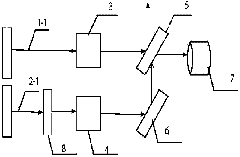
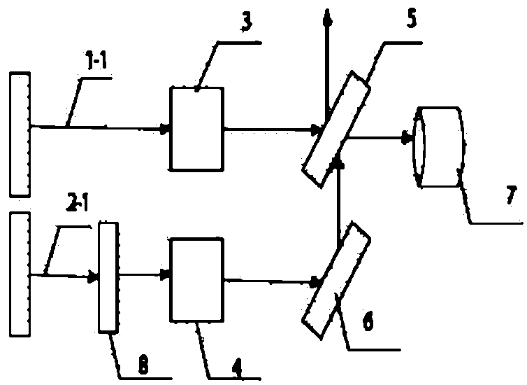
[0007] Specific implementation mode one: combine figure 1 Describe this embodiment, the all-optical fiber differential current measurement device based on the Faraday effect described in this embodiment includes: light source, photodetector 7 and two crystals, it also includes half-wave plate 8, first half mirror 5 And the first total mirror 6, the light source emits the first light beam 1-1 and obtains the first polarized light beam after the first crystal 3 is transmitted, and the first polarized light beam is incident on the first half mirror 5; The first half-mirror 5 emits the reflected light beam and the transmitted light beam, and the light source emits the second light beam 2-1, which is transmitted by the half-wave plate 8 and then enters the second crystal 4, and obtains the second polarized light beam after being transmitted by the second crystal 4, The second polarized light beam is incident on the first total reflection mirror 6, and the first total reflection mir...

specific Embodiment approach 2

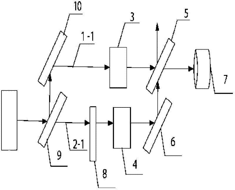
[0009] Specific implementation mode two: combination figure 2 Describe this embodiment, the difference between this embodiment and the Faraday effect-based all-fiber differential current measurement device described in Embodiment 1 is that it also includes a second half mirror 9 and a second total mirror 10, and the light source emits The light beam is incident on the second half-mirror 9 and sends a transmitted light beam and a reflected light beam. The transmitted light beam is the second light beam 2-1, and the reflected light beam sends a reflected light beam after the second total reflection mirror 10. The reflected light beam is the first beam 1-1.

[0010] There is one light source in this embodiment, and the first light beam 1-1 and the second light beam 2-1 are emitted by one light source.

specific Embodiment approach 3

[0011] Embodiment 3: The difference between this embodiment and the Faraday effect-based all-fiber differential current measurement device described in Embodiment 1 or 2 is that the transmission of light is transmitted in a polarization-maintaining optical fiber.


PUM


Abstract

The invention relates to a full-optical fiber difference stream measuring device based on the faraday effect, which relates to the filed of optical control. The invention solves the problems that light beams have strong electromagnetic interference in the existing light transmission process, in addition, the accuracy of using digital signals to judge the deflection angle is low, and the cost is high when two photoelectric detectors are used. The device comprises a light source, a photoelectric detector, crystals, a half wave plate, a semitransparent and half reflective mirror and a full reflective mirror, wherein polarized light beams are obtained after the system input light are transmitted through the crystals, the polarized light beams enter the semitransparent and half reflective mirror, the reflecting light beams and transmission light beams are emitted by the polarized light beams which are input through the semitransparent and half reflective mirror, the system input light beams enter the crystals after the transmission through the half wave plate, the polarized light beams are obtained through the transmission by the crystals, the polarized light beams enter the full reflective mirror, the reflecting light beams are emitted by the polarized light beams which are input through the full reflective mirror, and the transmission light beams exiting from the semitransparent part reflective mirror and the reflecting light beams reflected by the full reflective mirror are gathered to a light input end of the photoelectric detector. The device of the invention can be widelyapplied to the filed of optical control.

Description

technical field [0001] The invention relates to the field of optical control. Background technique [0002] At present, the detection instrument is a light intensity detection device after the light beam passes through an optical current transformer. The photoelectric converter in the light intensity detection device changes under the mutual inductance of the current, so that the light beam passing through the two photoelectric converters changes. The photoelectric converter then compares the received two beams of light with digital signals. If there is a difference between the two digital signals, it means that the light beam passing through the photoelectric converter is also changed due to an abnormal current in the transmission of light. , thus starting the current protection device. The disadvantages of the existing technology are: the cost of using two photodetectors is high, and they are subject to strong electromagnetic interference during use, and the errors that o...

Claims


Application Information

Patent Timeline
Patent Type & Authority Patents(China)
IPC IPC(8): G01R15/24
Inventor 郭志忠申岩张国庆于文斌路忠锋
Owner HARBIN INST OF TECH
Why Eureka
Try Eureka