Clock signal generating circuit

a clock signal and generating circuit technology, applied in the direction of generating/distributing signals, instruments, pulse techniques, etc., can solve the problems of interference signals, interference signals may interfere with the operation of nearby devices, and distortion of high-frequency clock signals

Inactive Publication Date: 2009-04-07
HON HAI PRECISION IND CO LTD
View PDF3 Cites 0 Cited by
  • Summary
  • Abstract
  • Description
  • Claims
  • Application Information

AI Technical Summary

Benefits of technology

[0001]The present invention relates to a clock signal generating circuit, and particularly to a clock signal generating circuit causing little electromagnetic interference.

Problems solved by technology

However, interference signals are also produced in a high-frequency clock signal generator, directly or via the connected supply or signal lines, in a wide frequency range.
The interference signals may interfere with the operation of nearby devices.
However, the EMC filters can cause distortion of high-frequency clock signals.

Method used


Image

  • Clock signal generating circuit
  • Clock signal generating circuit
  • Clock signal generating circuit

Examples


Embodiment Construction

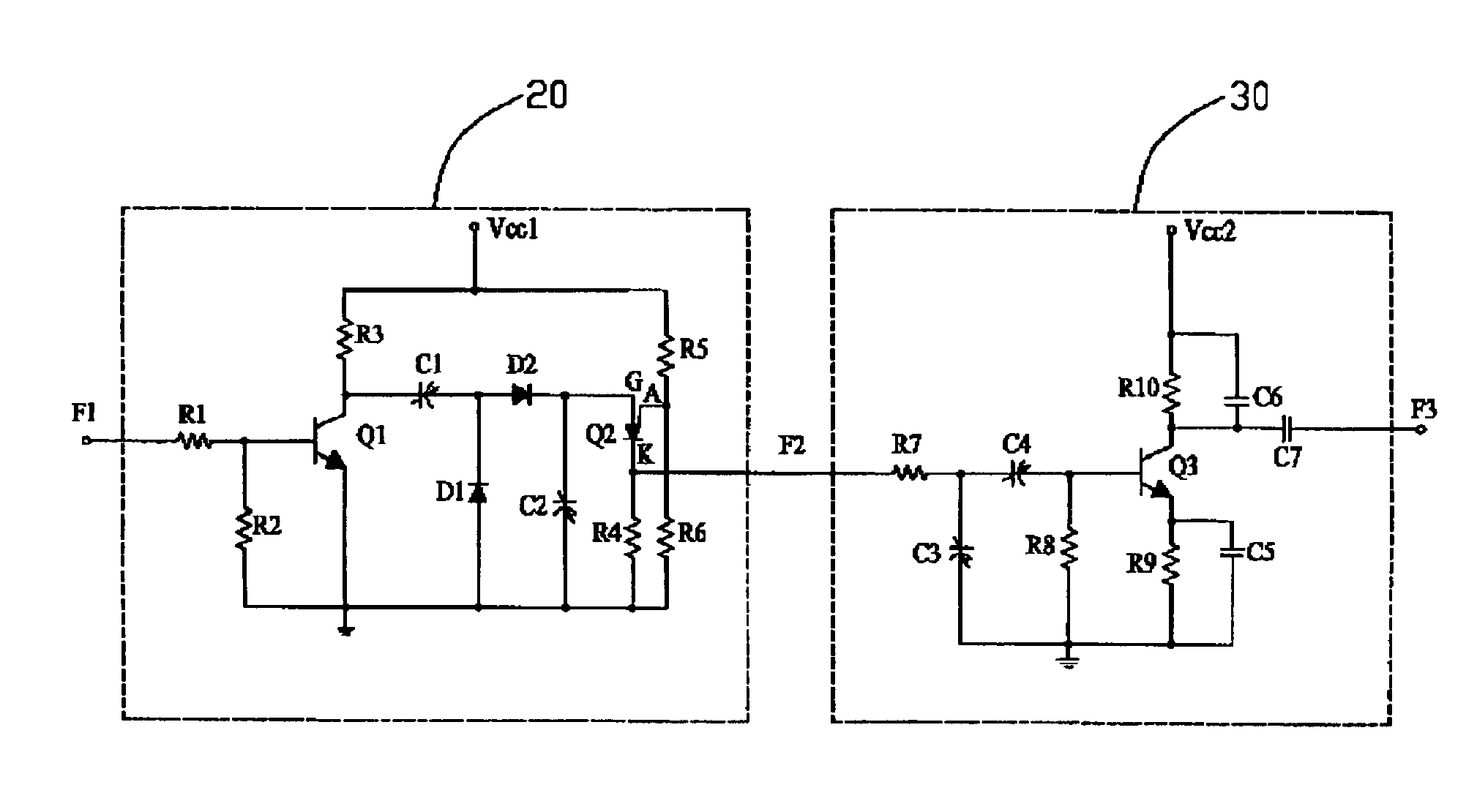
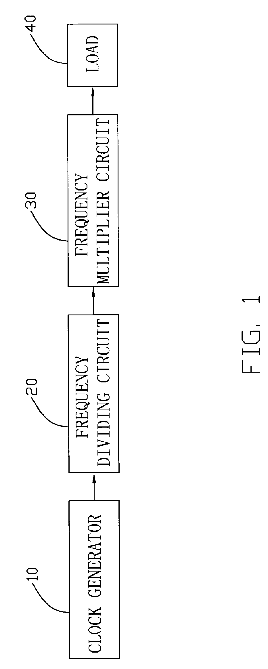
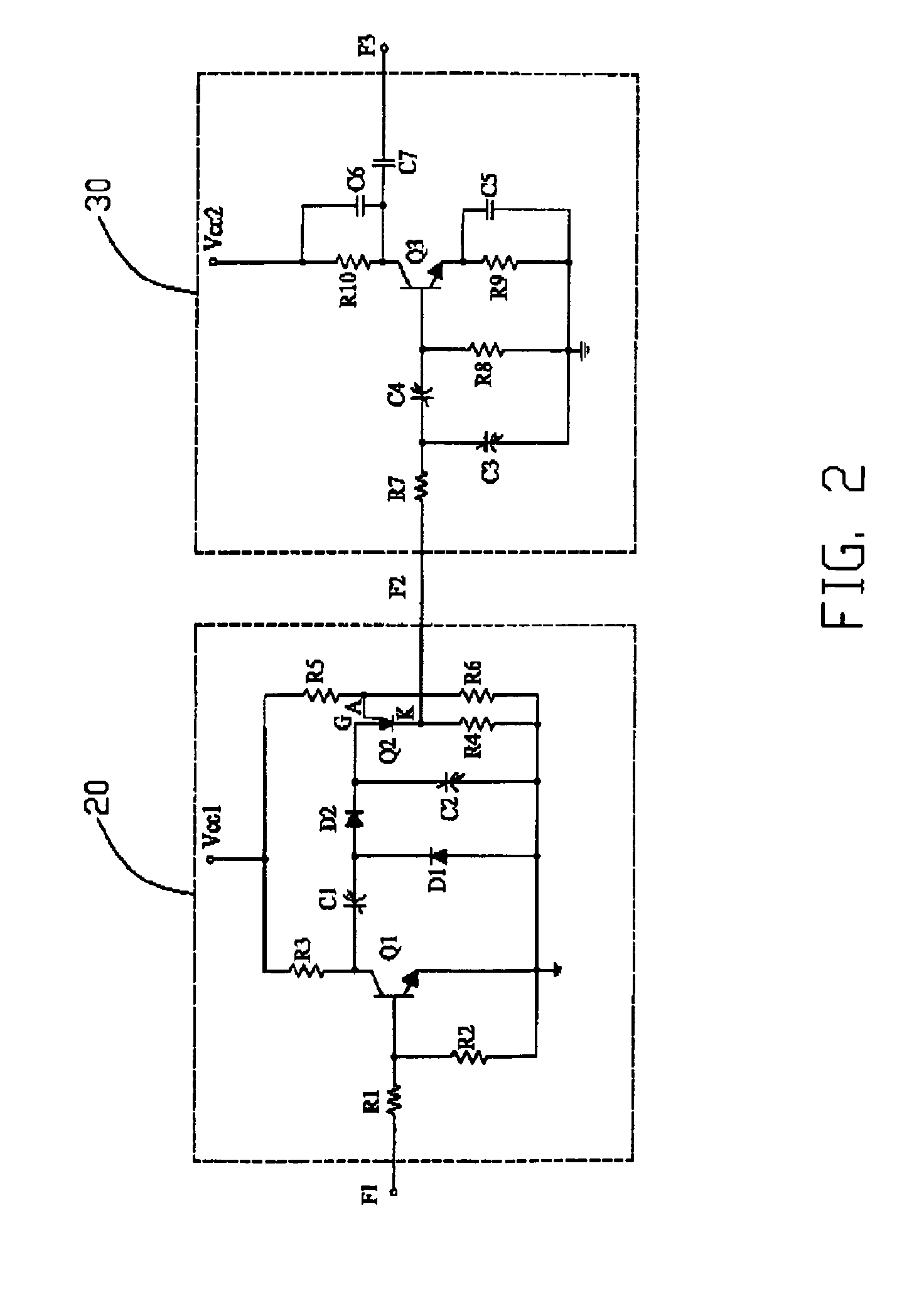
[0009]FIGS. 1-2 show a clock signal generating circuit, in accordance with a preferred embodiment of the present invention. The clock signal generating circuit provides a system clock signal F3. The clock signal generating circuit includes a clock signal generator 10, a frequency dividing circuit 20, and a frequency multiplier circuit 30. The clock signal generator 10 generates a first clock signal F1 having a predetermined frequency f1. The frequency dividing circuit 20 receives the first clock signal F1, and provides a second clock signal F2 with a frequency f2 that is lower than the predetermined frequency f1 of the first clock signal F1. The frequency multiplier circuit 30 receives the second clock signal F2, and provides the system clock signal F3, resuming the predetermined frequency f1, to a load 40.

[0010]FIG. 2 shows the frequency dividing circuit 20 and the frequency multiplier circuit 30 of FIG. 1. The frequency dividing circuit 20 includes a voltage input Vcc1, an NPN tra...


PUM


Abstract

A clock signal generating circuit is provided. The clock signal generating circuit includes a clock signal generator for generating a first clock signal having a predetermined frequency; a frequency dividing circuit receiving the first clock signal, for providing a second clock signal with a frequency that is lower than the predetermined frequency of the first clock signal; and a frequency multiplier circuit receiving the second clock signal, for providing a system clock signal resuming the predetermined frequency to a load.

Description

FIELD OF THE INVENTION[0001]The present invention relates to a clock signal generating circuit, and particularly to a clock signal generating circuit causing little electromagnetic interference.DESCRIPTION OF RELATED ART[0002]Use of digital clock-controlled signal-processing devices in various fields of application, particularly in computer systems, for the display or control of diverse functions requires clock signal generators. However, interference signals are also produced in a high-frequency clock signal generator, directly or via the connected supply or signal lines, in a wide frequency range. The interference signals may interfere with the operation of nearby devices.[0003]Some methods are known in the art whereby a plurality of electromagnetic compatibility (EMC) filters are used with the clock signal generator to reduce electromagnetic interference to adjacent electronic equipment. However, the EMC filters can cause distortion of high-frequency clock signals.[0004]What is n...

Claims


Application Information

Patent Timeline
Patent Type & Authority Patents(United States)
IPC IPC(8): G06F1/04H03K3/00
CPCG06F1/04H03B19/16
Inventor CHEN, CHUN-HUNG
Owner HON HAI PRECISION IND CO LTD
Why Eureka
Try Eureka