Device and method for symmetric load switching in an H bridge

a load switching and h-bridge technology, applied in the direction of process and machine control, dc motor rotation control, instruments, etc., can solve the problems of severe constraint in the control of the h-bridge, inconvenient constraint, and even prohibitive constrain

Active Publication Date: 2020-08-04
VITESCO TECH GERMANY GMBH
View PDF12 Cites 0 Cited by
  • Summary
  • Abstract
  • Description
  • Claims
  • Application Information

AI Technical Summary

Benefits of technology

[0017]There is therefore a need for an improved H-bridge device and a method for controlling such an H-bridge that allows use of a mode for controlling said H-bridge in accordance with the ‘lock anti-phase mode’ principle described above, providing additional means for detecting any risk of reversal of polarity and managing such a risk, without constricting the duty cycle of the pulse generator that is used.
[0018]By virtue of an aspect of the present invention, it is thus possible to control an H-bridge driving a load in a quick and safe manner. According to one embodiment, the H-bridge device according to an aspect of the invention furthermore emits little electromagnetic interference by virtue of the controlling of the potentials of the points of connection to the load.
[0031]This has the advantage of guaranteeing that the sum of the potentials at the connection points, on either side of the load, is constant and equal to the supply voltage, whether the switches are closed, in switching phase or open.
[0033]According to one embodiment, the reference magnitude is equal to 100 μA. This makes it possible to ensure that the current flowing through each switch is greater than this reference current, so as to prevent any reversal of polarity at the terminals of the load.

Problems solved by technology

Such a reversal of polarity in the motor M, if it were to occur, would specifically be liable to damage said motor M, as it would cause an undesired reversal of its direction of rotation.
This requirement to avoid causing a reversal of polarity in the motor M leads to a severe constraint in the controlling of the H-bridge.
This constraint constitutes a highly inconvenient drawback, and one that is even prohibitive when it is necessary to control an H-bridge driving a DC current electric motor in a motor vehicle.

Method used


Image

  • Device and method for symmetric load switching in an H bridge

Examples


Embodiment Construction

[0048]An aspect of the invention is presented mainly for the purpose of an application in an integrated circuit comprising an H-bridge driving an electric motor in a motor vehicle. However, other applications are also targeted by an aspect of the present invention, in particular in the context of driving any type of electrical load by way of an H-bridge.

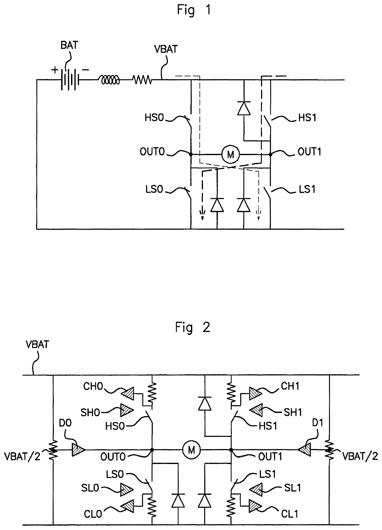
[0049]FIG. 1 represents the prior art and shows an H-bridge driving a load M. FIG. 1 has already been described above.

[0050]With reference to FIG. 2, the H-bridge device according to an aspect of the invention, in addition to the one described above to illustrate the prior art, comprises independent comparators CH0, CH1, CL0, CL1 monitoring the magnitude of the current flowing through each of said switches HS0, HS1, LS0, LS1 and also, according to the embodiment that is shown, independent means SH0, SH1, SL0, SL1 for controlling the current and voltage slopes at each switch HS0, HS1, LS0, LS1.

[0051]Controlled in ‘lock anti-phase mode...


PUM


Abstract

An H-bridge device and an associated method for controlling an H-bridge, driving a load such as a DC current electric motor, configured to prevent any reversal of polarity in the load in an unloading phase of said load, without having to limit use of the pulse generator supplying said H-bridge in terms of duty cycle. The H-bridge device includes independent comparators and independent slope control at each of the switches of the H-bridge. Furthermore, according to one aspect, the device includes ‘push-pull’ drivers imposing the potential VBAT / 2 at the connection points OUT0, OUT1, on either side of the load, in order to limit electromagnetic interference.

Description

CROSS REFERENCE TO RELATED APPLICATIONS[0001]This application is the U.S. National Phase Application of PCT International Application No. PCT / EP2017 / 050275, filed Feb. 7, 2017, which claims priority to French Patent Application No. 1650968, filed Feb. 8, 2016, the contents of such applications being incorporated by reference herein.FIELD OF THE INVENTION[0002]The invention relates to the field of integrated electronic circuits, in particular H-bridge devices as they are commonly known, that are intended to control the polarity at the terminals of a load by way of a plurality of switches that are commanded for example using a pulse generator.[0003]More precisely, the present invention endeavors to propose a device and an associated method aimed at optimizing symmetrical management of the switching of a load driven by way of such an H-bridge.BACKGROUND OF THE INVENTION[0004]The H-bridge is an electronic structure that is generally used to control the polarity at the terminals of a loa...

Claims


Application Information

Patent Timeline
Patent Type & Authority Patents(United States)
IPC IPC(8): H02P7/03H02P6/28G05F1/56H02P7/29H03K5/24G01R19/165
CPCH02P7/29G05F1/56H02P6/28H03K5/24H02P7/04G01R19/16552
Inventor BAVOIS, THIERRY
Owner VITESCO TECH GERMANY GMBH
Why Eureka
Try Eureka