Polarity switching circuit of power supply

A polarity conversion and circuit technology, which is applied to output power conversion devices, electrical components, regulating electrical variables, etc., can solve the problems of limited use range and inability to use, and achieve low circuit loss, small voltage difference, and low heat generation. Effect

Inactive Publication Date: 2011-10-26
林万炯
View PDF5 Cites 3 Cited by
  • Summary
  • Abstract
  • Description
  • Claims
  • Application Information

AI Technical Summary

Problems solved by technology

Its use is limited
The input voltage of many existing products is 24V, and the turn-on

Method used


Image

  • Polarity switching circuit of power supply
  • Polarity switching circuit of power supply
  • Polarity switching circuit of power supply

Examples


Embodiment Construction

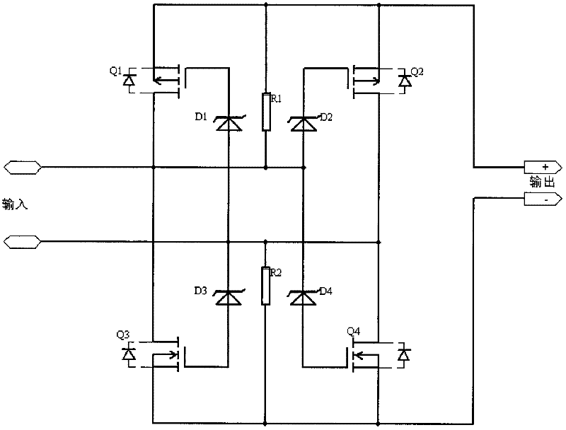
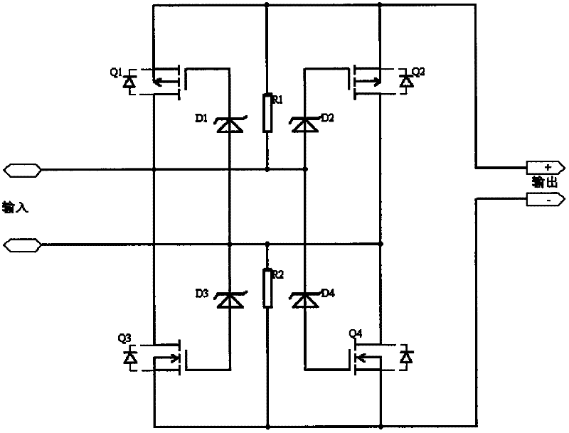
[0012] The present invention will be further described in detail below in conjunction with the accompanying drawings and embodiments.

[0013] see figure 1 The power supply polarity conversion circuit shown includes a first MOS transistor Q1, a second MOS transistor Q2, a third MOS transistor Q3, a fourth MOS transistor Q4, a first voltage regulator transistor D1, a second voltage regulator transistor D2, a third voltage regulator transistor The regulator tube D3, the fourth regulator tube D4, the first resistor R1, and the second resistor R2, wherein the first MOS tube Q1 and the second MOS tube Q2 are PMOS tubes, and the third MOS tube Q3 and the fourth MOS tube The transistor Q4 is an NMOS transistor, the drains of the first MOS transistor Q1 and the third MOS transistor Q3 are connected to the first pole of the input power supply, and the drains of the second MOS transistor Q2 and the fourth MOS transistor Q3 are connected to the first pole of the input power supply. The...


PUM


Abstract

The invention relates to a polarity switching circuit of a power supply, which is characterized by comprising four MOS (metal oxide semiconductor) tubes, four voltage-regulator tubes and two resistors, wherein drain electrodes of the first and the third MOS tubes are connected with a first pole of an input power supply; drain electrodes of the second and fourth MOS tubes are connected with a second pole of the input power supply; a grid electrode of the first MOS tube is connected with the first voltage-regulator tube and then the second pole of the input power supply; a source electrode of the first MOS tube is connected with the first resistor and then the first pole of the input power supply; a grid electrode of the third MOS tube is connected with the third voltage-regulator tube and then the second pole of the input power supply; a source electrode of the third MOS tube is connected with the second resistor and then the second pole of the input power supply; a grid electrode of the second MOS tube is connected with the second voltage-regulator tube and then the first pole of the input power supply; a grid electrode of the fourth MOS tube is connected with the fourth voltage-regulator tube and then the first pole of the input power supply; and a source electrode of the second MOS tube and a source electrode of the fourth MOS tube are the first pole and the second pole of the input power supply respectively. The polarity switching circuit of the power supply is low in circuit loss, low in radiation and small in differential pressure.

Description

technical field [0001] The invention relates to a power supply polarity conversion circuit. Background technique [0002] Several power polarity conversion circuits commonly used at present are: [0003] 1. Use bridge stacks or diodes to realize the automatic conversion circuit of input polarity. This circuit has a large input and output pressure difference and high heat generation. [0004] 2. Use relays to realize automatic polarity conversion circuits, which are usually large in size. [0005] 3. Use MOS tube to realize polarity conversion circuit, as attached figure 2 As shown, the circuit requires that the turn-on voltage of the MOS tube must be higher than the input voltage, otherwise the MOS tube will be damaged. Its scope of use is limited. The input voltage of many existing products is 24V, and the turn-on voltage of many commonly used MOS transistors is ±20V, so this circuit cannot be used. Contents of the invention [0006] The technical problem to be solve...

Claims


Application Information

Patent Timeline
IPC IPC(8): H02M3/00
Inventor 董建国尤晓波周伯友林万炯
Owner 林万炯
Why Eureka
Try Eureka