Voltage output circuit, driving circuit and switching power supply

A voltage output and drive circuit technology, applied in the field of voltage output circuits, drive circuits, and switching power supplies, can solve the problems of transformer volume and weight increase, cost increase, and audio noise generation, so as to reduce the number of turns and the radius of wires, reduce Small size, weight and cost, and the effect of solving audio noise problems

Active Publication Date: 2019-04-23
FUJIAN RAYNEN TECH
View PDF6 Cites 0 Cited by
  • Summary
  • Abstract
  • Description
  • Claims
  • Application Information

AI Technical Summary

Problems solved by technology

HID light is an excellent light source with high efficiency and energy saving, but it has a defect, that is, it takes about 2-3 minutes to turn on the power under normal circumstances before the light can slowly light up, sometimes when there is a sudden power failure and the power supply is restored immediately It takes 10-20 minutes to light up again, and it cannot be turned on at one point like incandescent lamps and halogen lamps, which is very unsuitable for occasions that require instant start lighting
[0003] The inventor of the present application found in the long-term research and development process that in the prior art, in order to increase the lighting speed of the HID lamp, the lighting circuit of the ballast is usually used

Method used


Image

  • Voltage output circuit, driving circuit and switching power supply
  • Voltage output circuit, driving circuit and switching power supply
  • Voltage output circuit, driving circuit and switching power supply

Examples


Example Embodiment

[0028] The application will be further described in detail below with reference to the drawings and embodiments. It is particularly pointed out that the following examples are only used to illustrate the application, but do not limit the scope of the application. Similarly, the following embodiments are only part of the embodiments of the present application, but not all of the embodiments. All other embodiments obtained by those of ordinary skill in the art without creative work shall fall within the protection scope of the present application.

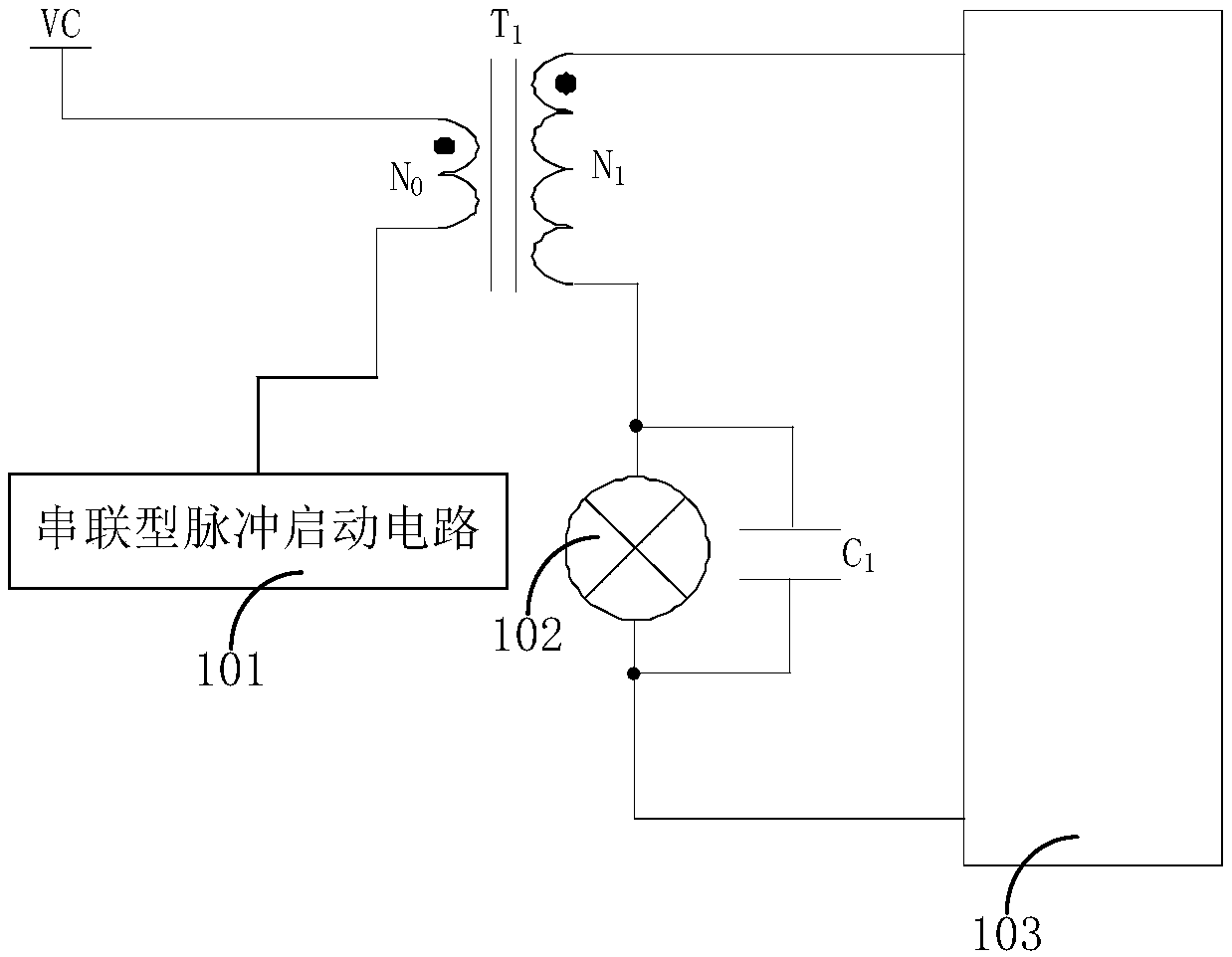
[0029] As the application fields of HID lamp sources such as metal halide lamps, high-pressure sodium lamps and mercury lamps become wider and wider, the consumption of low-frequency electronic ballasts is also increasing. Traditional low-frequency HID ballasts mostly use pulse transformers for lighting, and traditional low-frequency (tens of Hz to hundreds of Hz) HID ballast lighting circuits, that is, the driving circuit mostly uses p...


PUM


Abstract

The present invention discloses a voltage output circuit, a driving circuit and a switching power supply. The driving circuit is coupled to a light source, the driving circuit at least comprises a high-voltage output circuit and a pulse triggering circuit, the high-voltage output circuit comprises a transformer and at least one switch contact, the first input end of the transformer is connected with a power source voltage, the second input end of the transformer is connected with the pulse triggering circuit, the first output end of the transformer is connected with the first end of the at least one switch contact, the second output end of the transformer is connected with the second end of the at least one switch contact, the first end of the light source is connected with the second output end of the transformer, and the second end of the light source is coupled to the first output end of the transformer. When the light source is operated, the at least one switch contact is closed, and the working current of the light source flows through the at least one switch contact. Through the mode mentioned above, the loss can be reduced, the conversion efficiency can be improved, the size, the weight and the cost of the driving circuit can be reduced, the product miniaturization can be achieved, and the voice frequency noise problem caused by the transformer due to low-frequency commutation can be solved.

Description

Technical field [0001] This application relates to the technical field of switching power supplies, in particular to a voltage output circuit, a driving circuit, and a switching power supply. Background technique [0002] With the increasing shortage of power resources, the traditional light bulb electric lamp mode can no longer achieve the purpose of energy saving and emission reduction. In this case, HID lamps and other light sources are more and more widely used. HID lamp is an excellent light source with high efficiency and energy saving, but it has a defect, that is, it takes about 2-3 minutes to turn on the power under normal conditions to light up slowly. Sometimes when the power supply is restored immediately after a sudden power failure It takes 10-20 minutes to light up again, and it cannot light up at one point like incandescent lamps and halogen lamps. This is not suitable for occasions that require instantaneous lighting. [0003] In the long-term research and develop...

Claims


Application Information

Patent Timeline
IPC IPC(8): H05B41/18
CPCH05B41/18
Inventor 徐志望陈云辉叶跃明陈高江
Owner FUJIAN RAYNEN TECH
Why Eureka
Try Eureka