Supercharge Your Innovation With Domain-Expert AI Agents!

Centrifugal abrasive grain projectile device

A projection device and abrasive particle technology, applied in the direction of explosion generating device, abrasive material, metal processing equipment, etc., can solve the problems of time-consuming side liner, time-consuming replacement of impeller blades, huge weight of impeller, etc., and achieve the effect of easy replacement

Active Publication Date: 2011-10-26
SINTOKOGIO LTD
View PDF8 Cites 4 Cited by
  • Summary
  • Abstract
  • Description
  • Claims
  • Application Information

AI Technical Summary

Problems solved by technology

[0003] However, in the conventional abrasive centrifugal projection device configured as above, in addition to the time-consuming replacement of the side liners, there is a problem that the replacement of the impeller blades is also extremely time-consuming because the impeller is huge and heavy.

Method used


Image

  • Centrifugal abrasive grain projectile device
  • Centrifugal abrasive grain projectile device
  • Centrifugal abrasive grain projectile device

Examples


Embodiment Construction

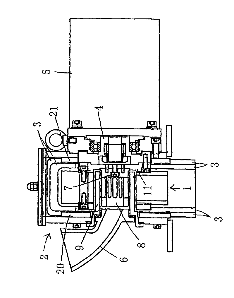
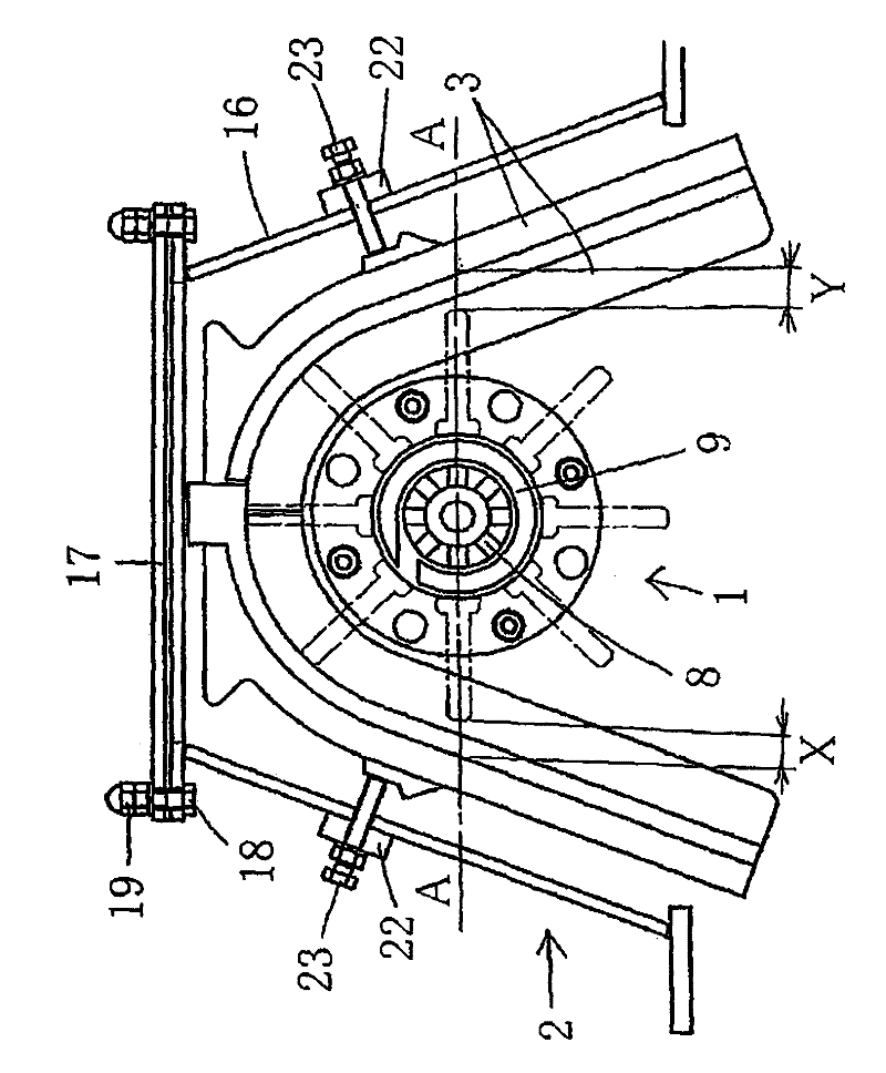
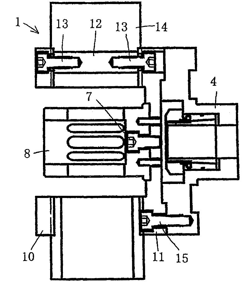
[0014] Below, combine Figure 1 ~ Figure 3 One embodiment of the abrasive centrifugal projection device to which the present invention is applied will be described in detail. Such as figure 1 as well as figure 2 As shown, the abrasive particle centrifugal projection device is composed of an impeller 1, an impeller cover 2, a side liner 3, a motor 5, a guide pipe 6, a distributor 8, and a control box 9, wherein the impeller 1 rotates and the abrasive particles are centrifugally projected , the impeller housing 2 surrounds the impeller 1 and prevents the scattering of abrasive grains to the outside, the side gasket 3 protects the side wall in the impeller housing 2 in the radial direction of the impeller 1 from the projection of abrasive grains, the motor 5 is fixedly arranged, and The impeller 1 is installed on the motor 5 via the hub 4 fitted to the output shaft of the motor; the guide pipe 6 is installed on the impeller housing 2 and guides the abrasive grains into the imp...


PUM


Abstract

The present invention relates to a centrifugal abrasive grain projectile device centrifugally projecting the abrasive grains through the rotation of an impeller, wherein the impeller is constructed by multiple impeller blades being attached radially at prescribed intervals between a facing pair of disk-shaped side plates, the impeller is attached to a hub fitted on the output shaft of an electricmotor, the impeller is enclosed by an impeller cover, and abrasive particles are shot centrifugally as the impeller is rotated. A side liner (3) having a U-shaped cross-section, which overall forms an upside-down widening U-shape and is split into two sections at the top part, and that is used to protect the side wall of the impeller cover (2) from the abrasive grains which are shot by the impeller (1), is attached to and can be detached from the inside of the impeller cover (2). The impeller (1) is fastened to the hub (4) by screwing a bolt (15), which is inserted from the inside of a side plate (11), into the hub (4). The outer diameter of the impeller (1) is a maximum of 200 mm.

Description

technical field [0001] The present invention relates to an abrasive particle centrifugal projection device. More specifically, it relates to an abrasive particle centrifugal projection device in which a pair of disk-shaped side plates facing each other with a desired interval are spaced radially apart from each other. A plurality of impeller blades are attached to form an impeller, and the impeller is mounted on a hub fitted to the output shaft of the motor. The impeller is surrounded by an impeller cover, and abrasive grains are centrifugally projected by the rotation of the impeller. Background technique [0002] Conventionally, as one of such devices, there is a device disclosed in Japanese Patent No. 4085353 . In this device, the impeller cover is protected by a plurality of divided gaskets, and the impeller cover surrounds the impeller composed of the first and second two impeller side plates and a plurality of impeller blades and mounted on the front end of the rotatin...

Claims


Application Information

Patent Timeline
Patent Type & Authority Applications(China)
IPC IPC(8): B24C5/06
CPCB24C5/062B24C5/066B24C5/06
Inventor 伊藤将克岩田恭一志贺雅治
Owner SINTOKOGIO LTD
Features
  • R&D
  • Intellectual Property
  • Life Sciences
  • Materials
  • Tech Scout
  • Unparalleled Data Quality
  • Higher Quality Content
  • 60% Fewer Hallucinations
Learn More