
Accumulator

A technology of accumulator and shell, applied in the direction of accumulator device, actuator accumulator, fluid pressure actuating device, etc., can solve the problems of high rupture pressure and wrong valve opening.

Active Publication Date: 2011-10-26
EAGLE INDS
View PDF1 Cites 23 Cited by
  • Summary
  • Abstract
  • Description
  • Claims
  • Application Information

AI Technical Summary

Problems solved by technology

[0005] However, in the prior art described above, as described above, since the emergency safety mechanism 62 is composed of the rupture plate 61d partially provided on the peripheral surface of the support cylinder 61 on the circumference, the rupture pressure is relatively high (requiring The large pressure to the extent that the metal plate is broken), so there is a discomfort that the emergency safety mechanism 62 will not operate when a considerable high pressure cannot be reached.
In addition, it is conceivable to provide a fusible plug or a valve instead of the rupture plate 61d, but in the fusible plug, the plug itself will not operate unless it reaches a high temperature, and in the valve, due to its mechanical structure, it will not be activated in an emergency. Mis-opening the valve (misoperation)

Method used


Image

  • Accumulator
  • Accumulator
  • Accumulator

Examples


Embodiment

[0072] Embodiments of the present invention will be described below with reference to the accompanying drawings.

no. 1 example

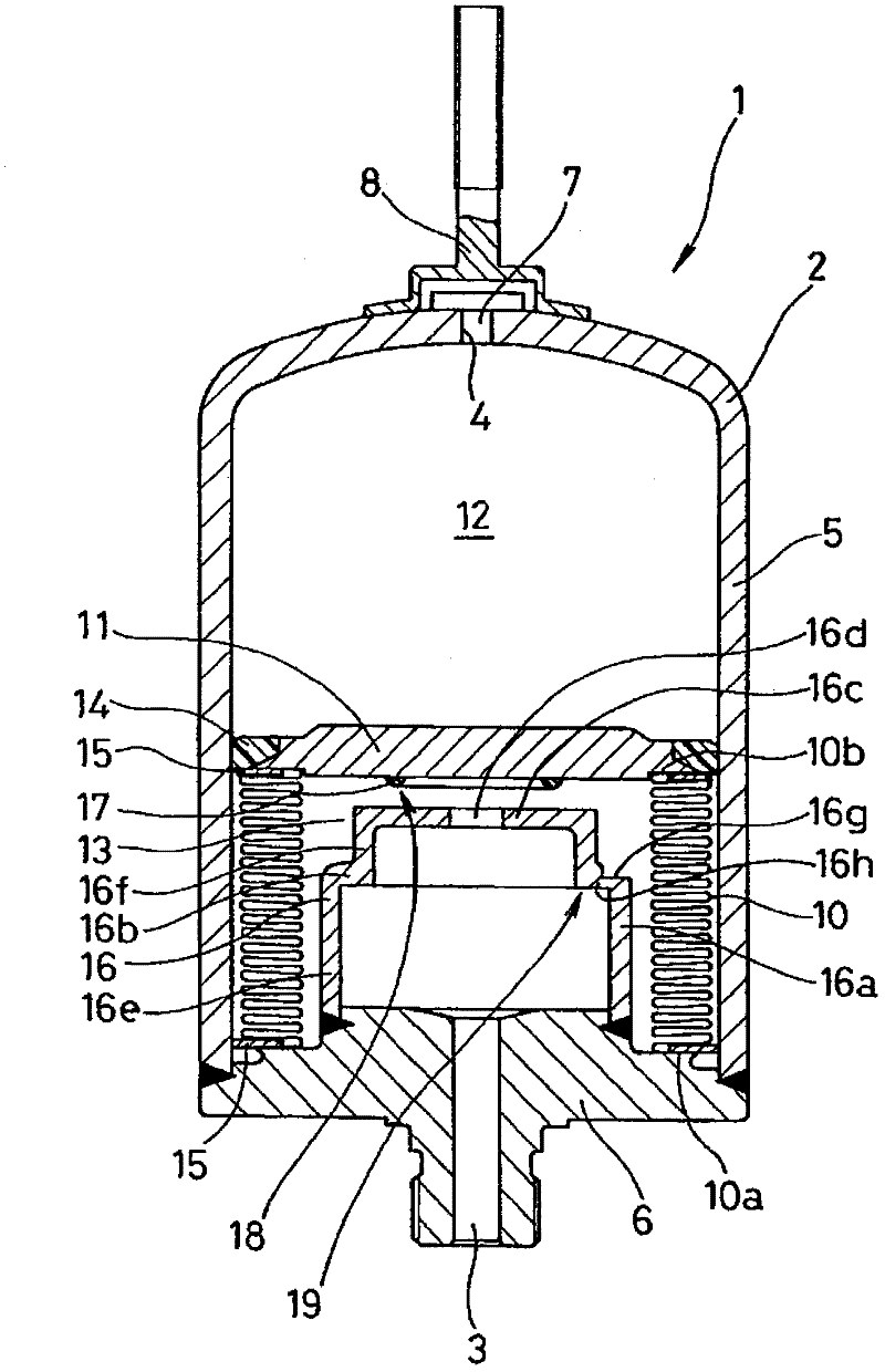
[0074] figure 1 A cross section of the accumulator 1 according to the first embodiment of the present invention is shown. The accumulator 1 according to this embodiment is a metal bellows type accumulator using a metal bellows as the bellows 10, and is configured as follows.

[0075] That is, firstly, an accumulator case 2 having one end (lower end in the figure) provided with an oil injection port 3 connected to a pressure pipe not shown in the figure, and the other end (upper end in the figure) provided with a gas inlet 4 is provided. A bellows 10 and a bellows cover 11 are arranged inside the housing 2, and the inner space of the housing 2 is divided into a gas chamber 12 filled with high-pressure gas (such as nitrogen) and a liquid chamber 13 communicating with the oil nozzle 3. Although it has been described that the housing 2 is composed of a bottomed cylindrical housing 5 and an oil nozzle member 6 fixed (welded) to an opening at one end of the housing 5, the componen...

no. 3 example

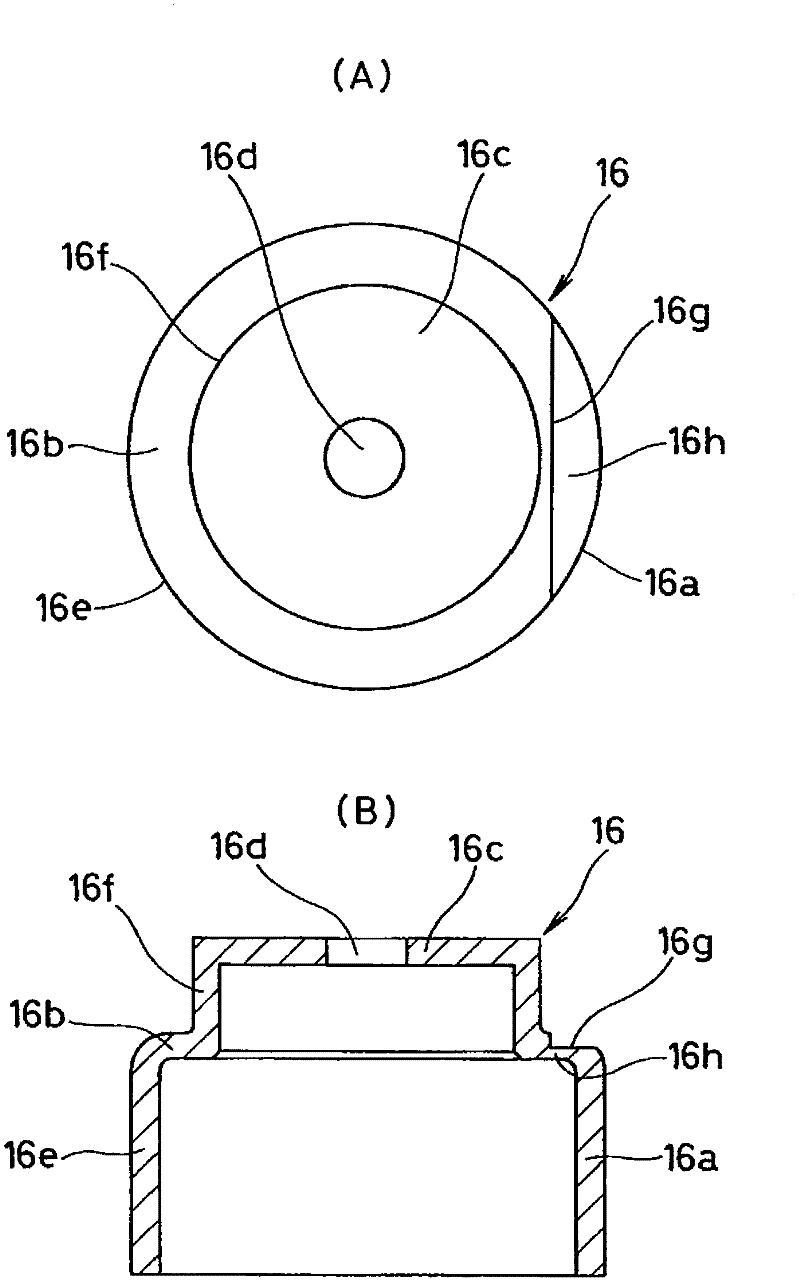
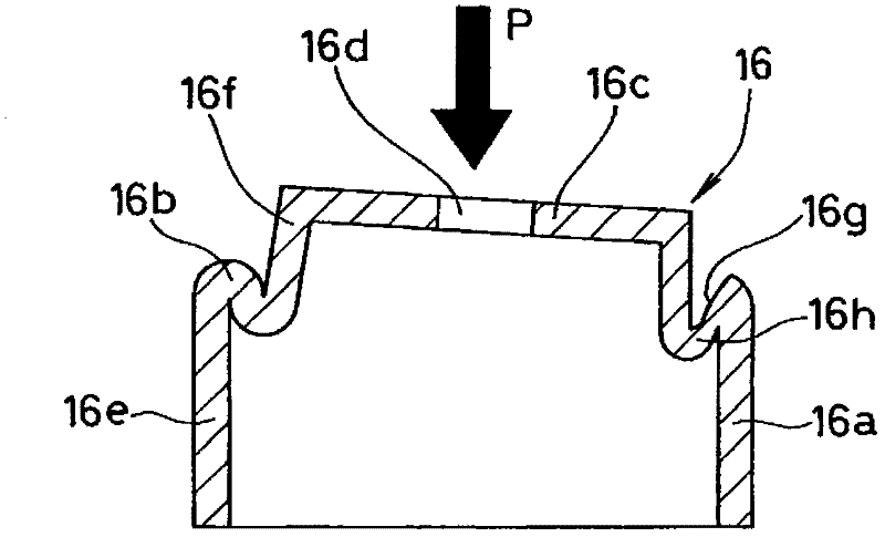
[0093] In addition, if figure 2 As shown in (A), in this embodiment, the planar shape of the notch portion 16g for forming a part of the thin wall portion 16h on the circumference is set to be arcuate, but, as Figure 4 As shown, as the second embodiment, it can also be set as a plane arc shape. In addition, in this embodiment, the notch portion 16g for forming the thin-walled portion 16h on a part of the circumference is provided on the outside (upper side) of the step difference 16b, however, as Figure 5 As shown, as the third embodiment, it may be installed on the inside (lower side) of the step difference 16b, or may be installed on both the outside (upper side) and the back side (lower side) of the step difference 16b.


PUM


Abstract

An accumulator provided with an emergency safety mechanism capable of being activated at a pressure lower than the pressure in the case in which a stay is provided with a rupture plate. In order to achieve the object, an accumulator comprises: an accumulator housing; a stay having a liquid inlet / outlet provided in the end surface of the tip of a stepped tubular section of the stay; a bellows equipped with a bellows cap; a safety mechanism provided in preparation for pressure reduction; and an emergency safety mechanism configured in such a manner that, in an emergency such as occurrence of a fire, the bellows cap or a member held by the bellows cap is caused to press the stay by the pressure in the housing, said pressure being high due to the occurrence of a fire, to cause the stay to be buckled at the step, opening a liquid chamber. A thin-walled section is provided at a circumferential part of the step of the stay so that, in an emergency, the end surface of the stay can easily tilt when the stay is pressed by the bellows cap to be buckled at the step.

Description

technical field [0001] The invention relates to an accumulator used as a pressure accumulator or a pulsation pressure attenuation device or the like. The accumulator of the present invention is used, for example, in hydraulic piping and the like in vehicles such as automobiles. Background technique [0002] Since before, as Figure 11 As shown, there is known an accumulator 51 having a structure in which an energy accumulator is provided with an oil injection port 53 connected to a pressure piping (not shown) and a gas sealing port 54 via a bellows 55 with a bellows cover 56 . The inner space of the device housing 52 is divided into a gas chamber 57 filled with gas and a liquid chamber 58 connected to the oil nozzle 53. The bellows cover 56 moves in such a way that the gas pressure and the liquid pressure are balanced, and the expansion and contraction of the bellows 55 , and perform a pressure accumulation operation or a pulsation pressure attenuation operation (refer to P...

Claims


Application Information

Patent Timeline
IPC IPC(8): F15B1/08
CPCF15B1/103F15B20/00F15B2201/205F15B2201/3153
Inventor 有川达浩太田隆水谷英二细井则行
Owner EAGLE INDS
Learn More