Eureka AIR delivers breakthrough ideas for toughest innovation challenges, trusted by R&D personnel around the world.

Method for bending and forming metal pipe by placing steel balls inside

A metal pipe, bending forming technology, applied in the field of metal pipe built-in steel ball bending forming, to achieve the effect of easy sealing and removal, large supporting force, and restraining the collapse of the outer wall of the forming

Inactive Publication Date: 2013-01-16
GUILIN UNIV OF ELECTRONIC TECH
View PDF6 Cites 2 Cited by
  • Summary
  • Abstract
  • Description
  • Claims
  • Application Information

AI Technical Summary

Problems solved by technology

Chinese patent CN 101433927A discloses a U-shaped tube micro-radius bending method in which steel balls are filled in metal tubes for bending and forming. The patent only focuses on the bending of U-shaped tubes. After filling with steel balls, the end of the tube is closed for bending; This method uses pipe end sealing instead of directly sealing and pressing the steel ball, so the resulting elbow will have a certain degree of ellipse at the bending neck, and a full circle processing is required after the bending is completed.

Method used


Image

  • Method for bending and forming metal pipe by placing steel balls inside
  • Method for bending and forming metal pipe by placing steel balls inside

Examples


Embodiment Construction

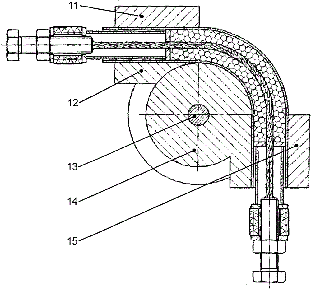
[0017] refer to figure 1 The closed pressure transmission structure at both ends of the metal pipe built-in steel ball consists of tension screw 1, nut 2, rubber spring 3, steel wire rope 4, force transmission tube 5, retaining ring 6, steel ball 7, pipe material 8, inner gasket 9 and outer Composed of gasket 10, the retaining ring 6 is placed in the pipe 8, the steel wire rope 4 penetrates into the pipe 8, and passes through the center hole of the retaining ring 6, one end of the steel wire rope 4 is connected with the tension screw 1, and the tension screw 1 and the nut 2 are movable Connection, the rubber spring 3 is sandwiched between the inner gasket 9 and the outer gasket 10 on the nut 2, one end of the power transmission tube 5 is firmly connected with the inner gasket 9, and the other end is closely connected to the top of the retaining ring 6, and the end of the retaining ring 6 There are built-in steel balls 7 between them, and the advance and retreat of the tension ...


PUM

PropertyMeasurementUnit
diameteraaaaaaaaaa

Abstract

The invention discloses a method for bending and forming a metal pipe by placing steel balls inside. The method is characterized by comprising the following steps of: (1) filling small steel balls of different numbers and different sizes serving as a pressure transmitting medium into a pipe forming section; (2) applying pressure to retainer rings at two ends of the steel balls by using closed pressure transmitting structures, wherein the pressure is always parallel to the axis of the pipe; (3) putting the closed and pressed metal pipe on a pipe bending die or pipe bending equipment, applying pressure to one end of the metal pipe, and clamping the other end of the metal pipe for bending and forming; and (4) opening the closed pressure transmitting structures at the two ends of the steel balls after bending is finished, and pouring and recycling the steel balls. The method has the advantages that: the steel balls are used as the pressure transmitting medium for bending and forming of the pipe, so forming defects of pipe bending parts can be effectively inhibited, and compared with the conventional other pressure transmitting medium, the steel balls are placed, sealed and taken out conveniently, the supporting force is large, and the problems of environmental pollution and the like are not produced.

Description

technical field [0001] The invention relates to a bending forming method of a metal pipe, in particular to a bending forming method of a metal pipe with built-in steel balls. Background technique [0002] In recent years, pipe bending parts, especially thin-walled pipe fittings, have been used in gas and liquid transportation pipelines and in the automotive industry, nuclear power, Aerospace and other high-tech fields have broad application prospects. However, defects such as outer wall collapse, inner wall wrinkling, section distortion, and springback are prone to occur during the bending process of the pipe, which affects the use of bent pipe parts. [0003] At present, in order to avoid or reduce the occurrence of forming defects, it is often necessary to use a mandrel or add fillers to the pipe for bending in engineering. When using a mandrel, precise process parameters are required and the cost is high, and it is usually used for CNC bending forming. As for the filli...

Claims


Application Information

Patent Timeline
Patent Type & Authority Patents(China)
IPC IPC(8): B21D9/15B21D9/12
Inventor 杨连发石松朝
Owner GUILIN UNIV OF ELECTRONIC TECH
Why Eureka
Eureka Blog
Learn More