Cylindrical cam flapping wing driving mechanism

A technology of cylindrical cam and driving mechanism, which is applied in the field of miniature flapping wing aircraft, can solve the problems of complex control elements and feedback control systems, low aerodynamic efficiency, etc., and achieve the effects of improved stability, simple structure and light weight

Active Publication Date: 2011-11-02
NORTHWESTERN POLYTECHNICAL UNIV
View PDF5 Cites 45 Cited by
  • Summary
  • Abstract
  • Description
  • Claims
  • Application Information

AI Technical Summary

Problems solved by technology

[0005] In order to overcome the disadvantages of low aerodynamic efficiency or the need for complex control elements and feedback control systems in the prior art, the present invention provides a cylindrical cam flapping wing drive mechanism, which can simply and reliably realize complex planar flapping laws, and is suitable for micro flapping wings aircraft application

Method used


Image

  • Cylindrical cam flapping wing driving mechanism
  • Cylindrical cam flapping wing driving mechanism
  • Cylindrical cam flapping wing driving mechanism

Examples


Embodiment Construction

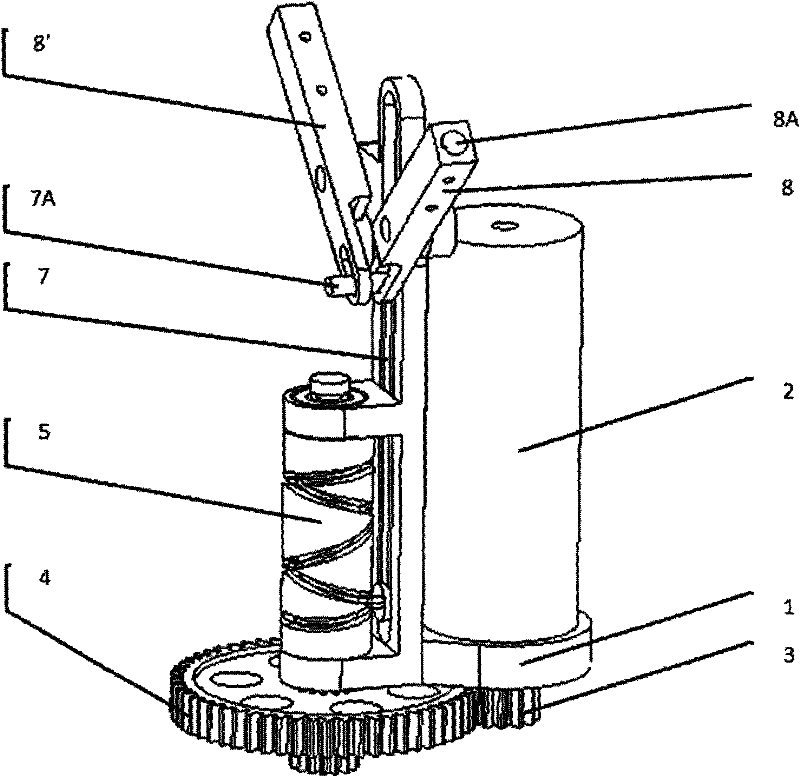
[0022] The cylindrical cam flapping wing driving mechanism of the present invention comprises a frame 1, a motor 2, a gear reducer, a cylindrical cam mechanism and a rocker mechanism.

[0023] The frame 1 is a left-right symmetrical overall structure made of duralumin alloy numerical control processing. The bottom surface has a transmission shaft hole 1A and a motor mounting hole. The axes of the two are parallel, and they are all located in the symmetrical plane of the frame. The frame has a guide rail perpendicular to the bottom surface. A connecting rod 7 parallel to the guide rail and capable of sliding in the guide rail is installed in the guide rail. There are left and right symmetrical rocker shaft holes on both sides of the guide rail. Coaxial No. 2 transmission shaft hole 1B. There are fixing holes at the rear and top of the frame, which are installed on the support frame of the flapping-wing aircraft fuselage by screws or pins.

[0024] The DC brushless motor 2 is i...


PUM


Abstract

The invention discloses a cylindrical cam flapping wing driving mechanism. A motor is fixed on a rack and drives a driving gear of a gear speed reduction device; a driven gear of the gear speed reduction device is coaxially and fixedly connected with a transmission shaft; the rack is fixedly connected with a guide rail which is parallel with a transmission shaft; the guide rail is internally provided with a connecting rod which can slide; one end of the connecting rod is articulated with a sliding plate, and the other end of the connecting rod is fixedly connected with a strut; a cylindrical cam is coaxially and fixedly connected at the outer side of the transmission shaft; one or more cycles of periodic curves are wound on the circumference of a cam slot; the sliding pate can slide in the cam slot; a swinging rod mechanism comprises two swinging arms, the middle part of each swinging arm is articulated with swinging arm shafts which are fixedly connected at two sides of the guide rail; one end of each swinging arm is provided with a sliding chute; the strut can slide in a reciprocating mode along the slide chute, and the other end of each swinging arm is connected with a flappingwing beam. By utilizing the mechanism provided by the invention, the complex plane flapping type can be realized, the structure is simple, the weight is light, the reliability is high, complex control is not required, and the mechanism is applicable to a micro flapping aircraft.

Description

technical field [0001] The invention relates to a flapping-wing driving mechanism, which can be applied to a miniature flapping-wing aircraft. Background technique [0002] The micro flapping wing aircraft is a new concept aircraft that imitates the flight of birds. It has the advantages of small size, light weight, flexible use, and high efficiency. If it is equipped with sensors and related data transmission and flight control systems, it will form a micro flapping wing unmanned machine platform, it will have broad application prospects. Around this subject, countries have developed controllable flying flapping-wing aircraft, among which the more successful ones are "Microbat" jointly developed by Aero Vironment of the United States and the University of California, and "Delfly" of Delft University in the Netherlands. However, these flapping-wing aircraft are far from The aircraft platforms of the practical UAV system have a certain distance. [0003] The current law of ...

Claims


Application Information

Patent Timeline
Patent Type & Authority Applications(China)
IPC IPC(8): B64C33/02F16H37/12
Inventor 王利光宋笔锋杨文青王进李洋高广林付鹏
Owner NORTHWESTERN POLYTECHNICAL UNIV
Why Eureka
Try Eureka