
Grinding disc devices for hand-operated grinding instruments

A grinding disc, hand-operated technology, applied in grinding/polishing safety devices, grinding/polishing equipment, grinding machines, etc., can solve problems such as material damage, and achieve the effect of simple manufacturing

Active Publication Date: 2016-02-24
ROBERT BOSCH GMBH
View PDF6 Cites 0 Cited by
  • Summary
  • Abstract
  • Description
  • Claims
  • Application Information

AI Technical Summary

Problems solved by technology

However, there is still the risk that local peak thermal loads lead to damage to the snap-fit ​​material made of plastic on the grinding disc

Method used


Image

  • Grinding disc devices for hand-operated grinding instruments

Examples


Embodiment Construction

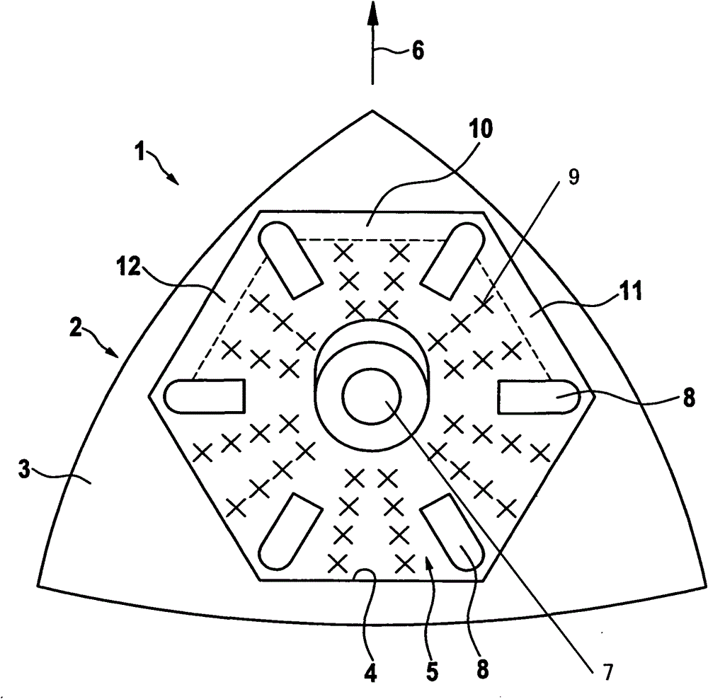
[0018] The figure shows a grinding disc arrangement 1 for a hand-operated grinding tool, in particular for an eccentric grinding machine. The grinding disc arrangement 1 comprises a motor-driven grinding disc 2 and a grinding disc 5 which is positively received in a recess 4 on the bottom surface 3 of the grinding disc 2 . The recess 4 on the base 3 has delimiting walls which delimit the removably inserted grinding disc 5 on all sides. The recess 4 is preferably embodied in such a way that the processing side of the inserted grinding disc 5 and the surrounding area of ​​the bottom surface 3 of the grinding disc 2 lie in a common plane. The recess 4 and the grinding disc 5 have a hexagonal contour in the exemplary embodiment. In contrast, the grinding disk 2 has an at least approximately triangular contour, wherein the outer triangular sides are curved concavely, that is to say radially outward. The machining direction is indicated by an arrow 6 ; the outer contour of the gri...


PUM


Abstract

The device (1) has a sand paper (5) arranged on bottom side of a sharpening plate (2) and connected with the sharpening plate by a Velcro(RTM: hook-and-loop fastener) that comprises two Velcro(RTM: hook-and-loop fastener) sections on top and bottom sides of the sharpening plate. The sections are extended to the sharpening plate over a partial flange of the bottom side of the sharpening plate. A part of the sharpening plate is formed on machining direction without the Velcro(RTM: hook-and-loop fastener).

Description

technical field [0001] The invention relates to a grinding disc arrangement for a hand-operated grinding tool. Background technique [0002] DE 10 2005 014 045 A1 describes a hand-held power tool in the form of an eccentric grinder with a grinding disc on the underside of which a grinding disc is fastened by means of a snap fit. Dust suction openings are formed in the grinding disc and the grinding disc, so that the grinding dust that occurs during tool processing can be sucked away. [0003] During tool machining, frictional heat is also generated on the underside of the grinding disc, although this frictional heat is partially dissipated by the air flow generated by the grinding dust extraction system. However, there is still the risk that local peak thermal loads lead to damage to the snap-fit ​​material made of plastic on the grinding disc. Contents of the invention [0004] The object of the invention is to construct a grinding disc arrangement for a hand-operated g...

Claims


Application Information

Patent Timeline
Patent Type & Authority Patents(China)
IPC IPC(8): B24B23/02B24B55/10B24D9/08
CPCB24D9/08B24B23/02
Inventor S·久里
Owner ROBERT BOSCH GMBH
Learn More