Supercharge Your Innovation With Domain-Expert AI Agents!

Fishbone-shaped groove rubber-coated roller

A rubber-covered roller and herringbone-shaped technology, which is applied in the direction of transportation and packaging, conveyor objects, rollers, etc., can solve the problems of easy aging, insufficient adhesion of the roller and the rubber surface, and low tear resistance, and achieve anti-tearing. The tearing ability is improved, the extrusion deformation is small, and the friction coefficient is not reduced.

Inactive Publication Date: 2011-11-09
SHANGHAI KEDA HEAVY IND GROUP
View PDF6 Cites 0 Cited by
  • Summary
  • Abstract
  • Description
  • Claims
  • Application Information

AI Technical Summary

Problems solved by technology

[0004] The purpose of the present invention is to provide a herringbone-groove rubber-coated roller to solve the problems of low tear resistance of the rubber-coated roller in the prior art, insufficient bonding of the roller and the rubber surface, and easy aging

Method used


Image

  • Fishbone-shaped groove rubber-coated roller
  • Fishbone-shaped groove rubber-coated roller
  • Fishbone-shaped groove rubber-coated roller

Examples


Embodiment 1

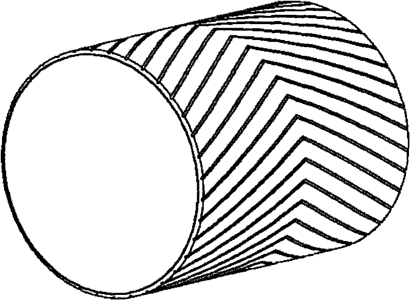
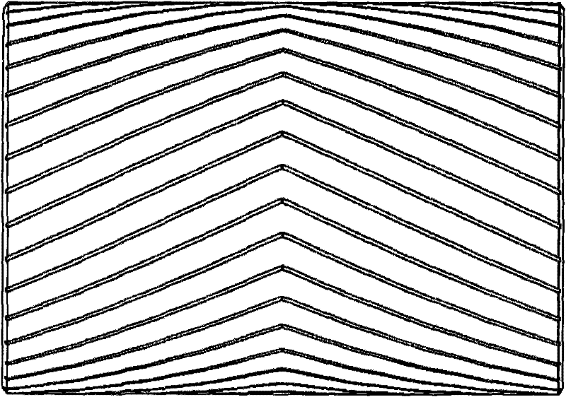
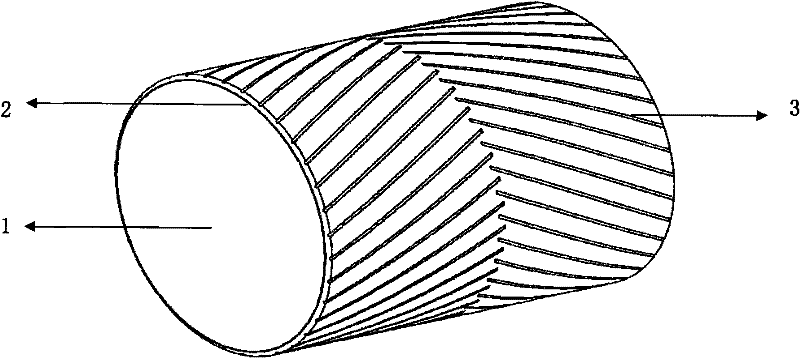
[0016] Such as image 3 As shown, the herringbone-groove rubber-covered roller involved in this embodiment includes a roller body 1 made of metal, and a layer of integral rubber-covered 2 is wrapped on the outer peripheral surface of the metal roller. Strip grooves 3 are provided on the left and right sides of the rubberized surface, and the grooves on the left and right sides are staggered at the center line of the drum body; the top view of the rubberized drum is shown in Figure 4 . When using the rubberized roller of this embodiment, since the strip grooves on the left and right sides of the surface of the roller do not intersect, the extrusion deformation of this type of rubberized rubber surface is smaller than that of the herringbone grooved rubber surface, and the tear resistance is improved; at the same time, the conveying When the belt is in contact with the surface of the pulley, the water and dirt on the surface of the rubberized pulley can be discharged from the ...

Embodiment 2

[0018] The herringbone groove rubberized roller involved in this embodiment includes a roller body 1, the roller body is made of metal, and a whole layer of rubberized rubber 2 is wrapped on the outer peripheral surface of the metal roller, and the rubberized surface The left and right sides are provided with strip grooves 3, and the grooves on the left and right sides are staggered at the center line of the drum body, and the lengths of the strip grooves on the left and right sides are the same. When using the rubberized roller of this embodiment, since the strip grooves on the left and right sides of the roller surface do not intersect, the extrusion deformation of this type of rubberized rubber surface is smaller than that of the herringbone grooved rubber surface, and the tear resistance is improved. At the same time, because The strip grooves on the left and right sides have the same length, which makes the manufacturing process more convenient and the force on the rubberi...


PUM


Abstract

The invention relates to a fishbone-shaped groove rubber-coated roller. The roller comprises a roller body, and a rubber coating fixed on the circumferential surface of the roller body, wherein strip grooves are formed on the left and right sides of the surface of the rubber coating and staggered in the center line of the roller body. The strip grooves on the left and right sides of the surface of the roller are uncrossed, so the rubber coating has lower extrusion deformation than a herringbone groove rubber surface, and tear resistance is improved; and when a conveying belt is contacted with the surface of the roller, water and dirt on the surface of the rubber-coated roller can be discharged into the strip grooves from the surface of the conveying belt through extrusion, so that the rubber-coated roller can be used in a wet environment and even a severer environment and is completely attached to a rubber belt, and the friction coefficient is not reduced.

Description

technical field [0001] The invention relates to a roller in the field of conveying machinery, in particular to a herringbone groove rubber-covered roller. Background technique [0002] The rubber-covered pulley is an important part and part of the belt conveyor system. The rubber-covered pulley can effectively improve the operation of the conveying system, protect the metal pulley from wear, prevent the conveyor belt from slipping, and make the pulley and the belt run synchronously, thus ensuring The belt runs efficiently and with a large capacity; the rubber lagging of the pulley can also effectively prevent the sliding friction between the pulley and the belt, reduce the material adhesion on the surface of the pulley, and thus reduce the deviation and wear of the belt. [0003] Chinese Invention Patent Application Publication CN1880196A (public date: December 20, 2006) discloses the following technical content: most of the rubber coating on the rubber coating drum in the p...

Claims


Application Information

Patent Timeline
IPC IPC(8): B65G39/07
Inventor 郁丽芳
Owner SHANGHAI KEDA HEAVY IND GROUP
Features
  • R&D
  • Intellectual Property
  • Life Sciences
  • Materials
  • Tech Scout
  • Unparalleled Data Quality
  • Higher Quality Content
  • 60% Fewer Hallucinations
Learn More