
An Improved Miniaturized Membrane Valve

A membrane valve and valve body technology, applied in the field of improved miniaturized membrane valves, can solve problems such as channel blockage, and achieve the effects of easy disassembly, reduced resistance, and convenient maintenance

Active Publication Date: 2019-02-01
GUANGZHOU INST OF ADVANCED TECH CHINESE ACAD OF SCI
View PDF11 Cites 0 Cited by
  • Summary
  • Abstract
  • Description
  • Claims
  • Application Information

AI Technical Summary

Problems solved by technology

[0005] In view of this, it is necessary to provide an easy-to-clean, easy-to-maintain, non-introduced impurity solution for the above-mentioned problems, which is conducive to improving the channel blockage caused by the extrusion deformation of the elastic film, reducing the resistance of liquid flowing through the channel, and improving Miniaturized Membrane Valve with Improved Performance of Membrane Valve

Method used


Image

  • An Improved Miniaturized Membrane Valve
  • An Improved Miniaturized Membrane Valve
  • An Improved Miniaturized Membrane Valve

Examples


Embodiment 1

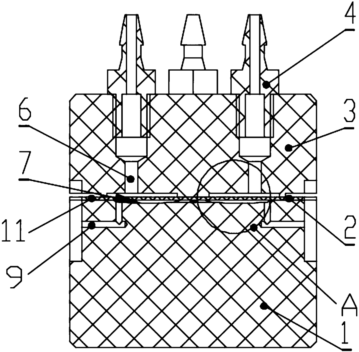
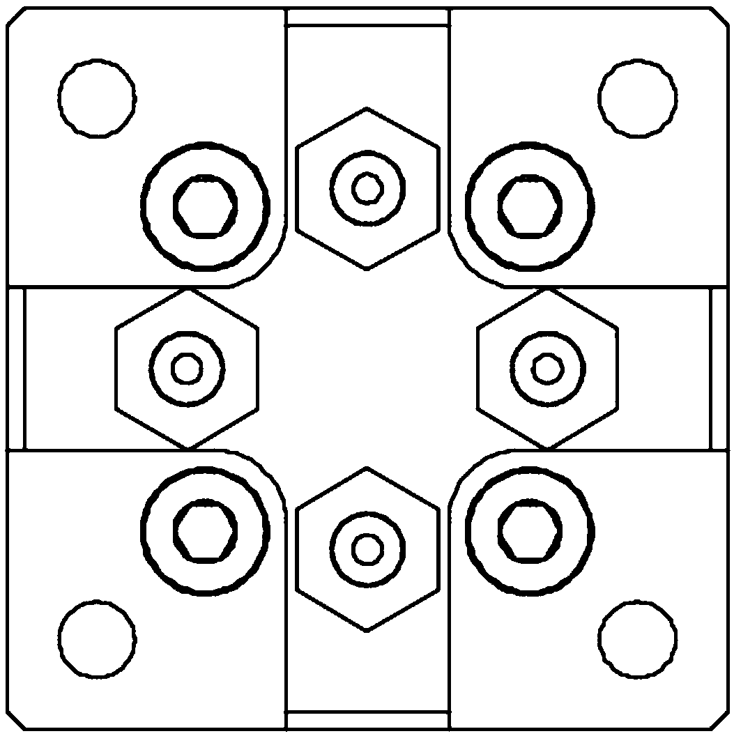
[0060] Such as Figure 1-8 As shown, it is a multi-channel valve. The valve system is arranged in a cross shape to form multiple channels, including an upper valve body 3, a lower valve body 1, and a flexible membrane 2 sandwiched between the upper and lower valve bodies. The flexible membrane 2 can It is made of raw rubber or silicon rubber; the upper and lower valve bodies are connected by four screws 5; the positions of the four screws 5 are evenly arranged in two diagonal directions.

[0061] The upper and lower valve bodies are provided with a valve system, and the valve system includes: a connector 4, an air pipeline 6, a fluid cavity 7, and a fluid pipeline 9; the connector 4 is installed on the upper valve body 3, and the upper end Protruding above the upper valve body 3, the lower end penetrates the upper valve body 3 and is connected with the built-in air pipeline 6 of the upper valve body 3, and the air pipeline 6 is connected to the upper surface of the flexible me...

Embodiment 2

[0069] Such as Figure 9-13 As shown, the main difference between this embodiment and Embodiment 1 is that the boss 11 is arranged on the surface of the lower valve body 1 , specifically located outside the edge of the fluid chamber 7 , and its functions and effects are the same.

[0070] As a further improvement, such as Figure 13-16 As shown, at least one barrier 12 (such as Figure 14 shown). The barrier 12 includes embedded limiting components or the flexible membrane 2 is partially thickened and rigidized. The barrier 12 prevents compressed air from flowing from one air line 6 into any adjacent air line 6 .

[0071] Described lower valve body 1 is also provided with groove 13 (as Figure 15 shown) for embedding the barrier 12 in the groove 13; or the partially thickened and rigidified flexible membrane 2 directly protrudes into the upper valve body 3 as the barrier 12 (as Figure 16 shown).

Embodiment 3

[0073] Such as Figure 17-27 As shown, the difference between this embodiment and Embodiment 1 or 2 is that the boss 11 is arranged on the upper valve body 3, the boss 11 includes a platform 16 and a protrusion 18, and the platform 16 is arranged on the protrusion 18; the height of the platform 16 is slightly lower than the protrusion 18, but protrudes from the surface of the valve body; a groove body 14 is set on the lower valve body 1, and the groove body 14 is arranged on the protrusion and On the other valve body opposite to the portion 18 , the groove body 14 is engaged with the protruding portion 18 .

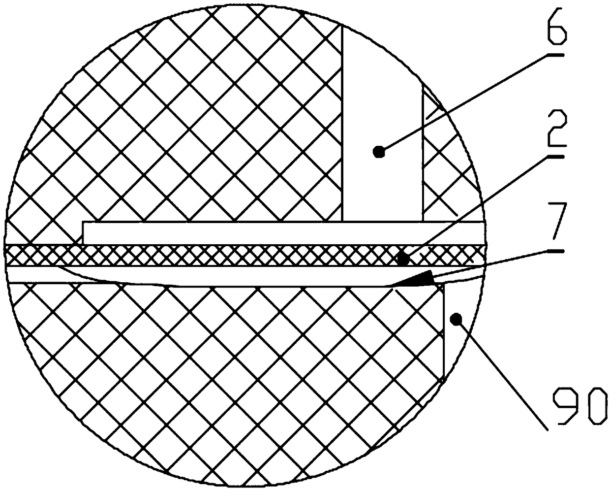
[0074] When the upper valve body 3 and the lower valve body 1 are pressed tightly, the protrusion 18 squeezes the flexible membrane 2 around the fluid chamber 7 into the groove body 14, thereby forming a stretching effect on the flexible membrane 2 above the fluid chamber 7, thereby It effectively prevents the flexible membrane 2 from being compressed and squeezed into t...


PUM


Abstract

The invention relates to the technical field of valves, and particularly discloses a small improved membrane valve. The small improved membrane valve comprises an upper valve body, a lower valve body and a flexible membrane, wherein the upper valve body and the lower valve body are connected with each other, and the flexible membrane is clamped between the upper valve body and the lower valve body. The upper valve body and the lower valve body are further provided with a valve system. The valve system comprises connectors, air pipelines, fluid cavities and fluid pipelines. The fluid cavities are formed in the lower valve body and communicate with one ends of the corresponding fluid pipelines, and the other ends of the fluid pipelines transversely extend to the outer side wall of the membrane valve. The fluid pipelines are arranged inside the lower valve body and bent in an L shape. Connecting ports corresponding to outlets of the fluid pipelines are arranged in the outer side face of the membrane valve. The inner surface of the upper valve body or the lower valve body is provided with bosses, and the height of the bosses is slightly smaller than the thickness of the flexible membrane in the natural relaxation process. The bosses are arranged at the positions corresponding to the outer sides of the edges of the fluid cavities in a surrounding mode, so that an enclosed space is formed. By the adoption of the membrane valve, the problem of channel blockage caused by elastic film compressional deformation can be better solved, the resistance of liquid flowing past channels is reduced, and the membrane valve performance is improved.

Description

technical field [0001] The invention relates to the technical field of valves, in particular to an improved miniaturized membrane valve. Background technique [0002] Miniature automated laboratory membrane valve equipment (for example, in the field of biology or bioengineering) requires a series of processing functions that can be easily combined into larger equipment, safe and easy to use and easy to clean. Typical processing functions of membrane valve devices include storing liquids, transferring liquids, switching between different liquid lines, catalyzing biomass within a reactor, heating, cooling, interacting with electrical currents or electromagnetic radiation. [0003] The elastic film of the existing miniaturized membrane valve is pressed in the middle by the upper and lower valve bodies, and the opening / closing of the passage is controlled by controlling the deformation of the elastic film through high-pressure gas. Under the pressing effect of the upper and low...

Claims


Application Information

Patent Timeline
Patent Type & Authority Patents(China)
IPC IPC(8): F16K7/12F16K11/02F16K27/02
CPCF16K7/123F16K11/022F16K27/0236
Inventor 王忠万玉明艾澈熙崔金明刘陈立袁海
Owner GUANGZHOU INST OF ADVANCED TECH CHINESE ACAD OF SCI
Learn More