Bidirectional-sensing compensating tank bearing and tank locking device for hoisting container

A sensing device and tank locking technology, which is applied in the field of cage receiving and compensating for locking the cage, can solve the problems of inability to detect the size of the tank supporting force and locking force of the equipment, the limited error height of the cage stopping the tank, and cumbersome operations, etc. Achieve the effect of shortening the lifting cycle time, improving the lifting efficiency and simple operation

Inactive Publication Date: 2011-11-09
徐州泰荣煤矿设备有限公司
View PDF5 Cites 8 Cited by
  • Summary
  • Abstract
  • Description
  • Claims
  • Application Information

AI Technical Summary

Problems solved by technology

[0005] 1. The operation requirements are high, and the tank stop position is required to be accurate (the error is only 40mm)
[0006] 2. The operation is cumbersome, and the winch needs to be reversed after loading and unloading
[0007] 3. It is not suitable for the existing winch electronic control system in my country. If you want to use this device, you must be equipped with a Siemens special electronic control system.
[0008] 4. The amount of basic engineering transformation is large and the cost is high
[0010] 1. Use the hydraulic cylinder to directly lock the cage, which requires high flow and pressure of the hydraulic system, so the action is very slow
[0011] 2. It can compensate for the limited height of the cage stop error, which cannot fully meet the elastic elongation requirements of large deep well wire ropes.
[0012] 3. It is impossible to detect the size of the equipment's tank-bearing force and tank-locking force

Method used


Image

  • Bidirectional-sensing compensating tank bearing and tank locking device for hoisting container
  • Bidirectional-sensing compensating tank bearing and tank locking device for hoisting container
  • Bidirectional-sensing compensating tank bearing and tank locking device for hoisting container

Examples


Embodiment Construction

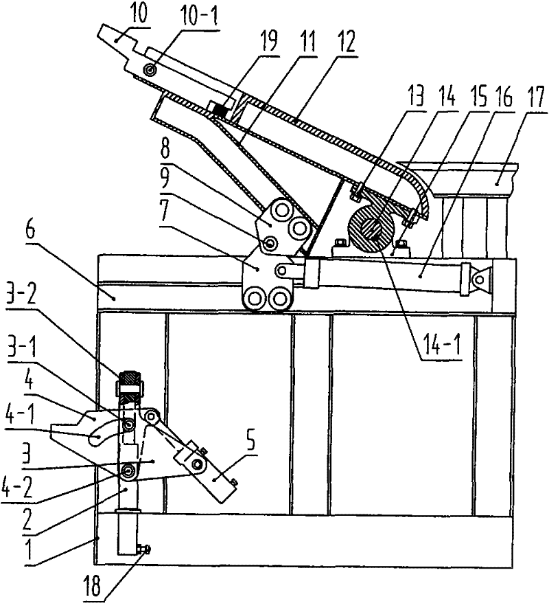
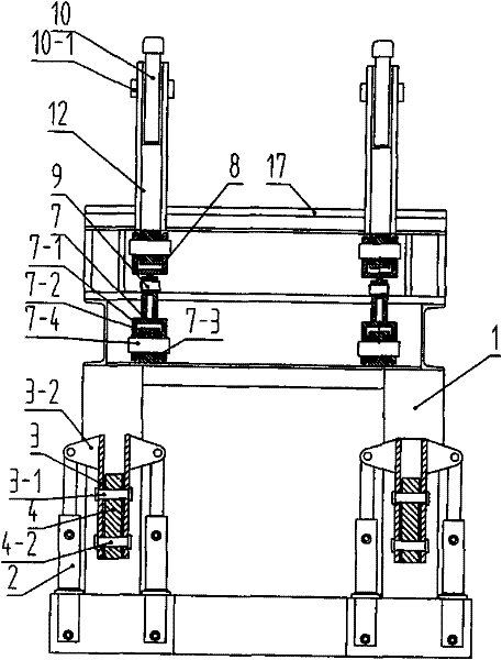
[0035] like figure 1 , figure 2 As shown: a two-way sensory compensation tank lock device for lifting containers includes: a frame 1, a tank support device installed inside the frame 1, and a tank lock device installed on the upper part of the frame 1; it is characterized in that: The load sensing device 18 is set on the device, and the tank locking device 19 is set on the tank locking device; the frame 1 is a steel rectangular frame;

[0036] The tank supporting device includes: a lifting cylinder 2, a lifting bracket 3, a supporting claw 4 and a conversion cylinder 5; the lifting bracket 3 is an asymmetrical triangular plate, and the upper part of the triangular plate vertically fixes the ear plate 3-2; The piston rod of the lift cylinder 2 is connected to the ear plate 3-2, and the cylinder body of the lift cylinder 2 is installed on the frame 1; the claw 4 is similar to a prismatic plate, and the claw 4 is clamped on the Between the two lifting brackets 3, the bottom of...


PUM


Abstract

The invention discloses a bidirectional-sensing compensating tank bearing and tank locking device for a hoisting container, relating to mining equipment. The bidirectional-sensing compensating tank bearing and tank locking device is composed of a rack, a tank supporting device and a tank locking device. The tank supporting device is provided with a bearing sensing device 18, and the tank locking device is provided with a tank locking sensing device 19. The tank supporting device comprises a hoisting cylinder 2, a hoisting support 3, a supporting claw 4 and a switching cylinder 5. A piston rodof the hoisting cylinder 2 is connected with a hoisting support 3, the supporting claw 4 is connected with the hoisting support 3, and the switching cylinder 5 is arranged between the supporting claw4 and the hoisting support 3. The tank locking device comprises a rocker arm 12, a pressure block 10, a lower slide 6, an upper slide 11 and a tank locking cylinder 16. The rocker arm 12 is arranged on the rack 1 by virtue of an upper support and a lower support, and the pressure block 10 is arranged at the outer end of the rocker arm. The rocker arm 12 can realize rotary tank locking by virtue of the upper slide, the lower slide, an upper pulley assembly, a lower assembly and a tank locking cylinder 16.

Description

technical field [0001] The invention relates to a mine equipment, in particular to a device suitable for receiving and compensatingly locking a cage when loading and unloading a large hoisting container (cage) in a mine with a depth of one thousand meters. Background technique [0002] During the loading and unloading process of the cage, a cradle device is required to connect the inner and outer lanes. In order to avoid the impact load directly acting on the cage, and to avoid the excessive elongation of the steel wire rope due to excessive load, a device for receiving the cage must be installed on the cradle. When the cage has a small load, the elastic expansion and contraction of the steel wire rope is small, and the equipment can enter and exit the cage smoothly. When large-load equipment (such as a heavy-duty flatbed truck with a maximum mass of more than 40 tons) enters and exits the cage, the elastic elongation of the steel wire rope is large (for deep wells, the elon...

Claims


Application Information

Patent Timeline
Patent Type & Authority Applications(China)
IPC IPC(8): B66B17/14
Inventor 陈利强王雷陈义强杨建奎李祝民李平
Owner 徐州泰荣煤矿设备有限公司
Why Eureka
Try Eureka