
Projector

A projection device and reflective technology, applied in projection devices, optics, instruments, etc., can solve the problems of low cost, achieve low cost, increase contrast, and improve projection quality

Inactive Publication Date: 2011-11-09
SHINYOPTICS
View PDF3 Cites 2 Cited by
  • Summary
  • Abstract
  • Description
  • Claims
  • Application Information

AI Technical Summary

Problems solved by technology

[0005] In view of various problems in the background technology, the present invention proposes a projection device as a realization method and basis for improving the above-mentioned shortcomings, which can improve the contrast, is not easy to produce interference phenomenon, and has low cost

Method used


Image

  • Projector
  • Projector
  • Projector

Examples


Embodiment Construction

[0064] The preferred embodiments of the projection device of the present invention will be described below with reference to the relevant drawings. For ease of understanding, the same components in the following embodiments are described with the same symbols.

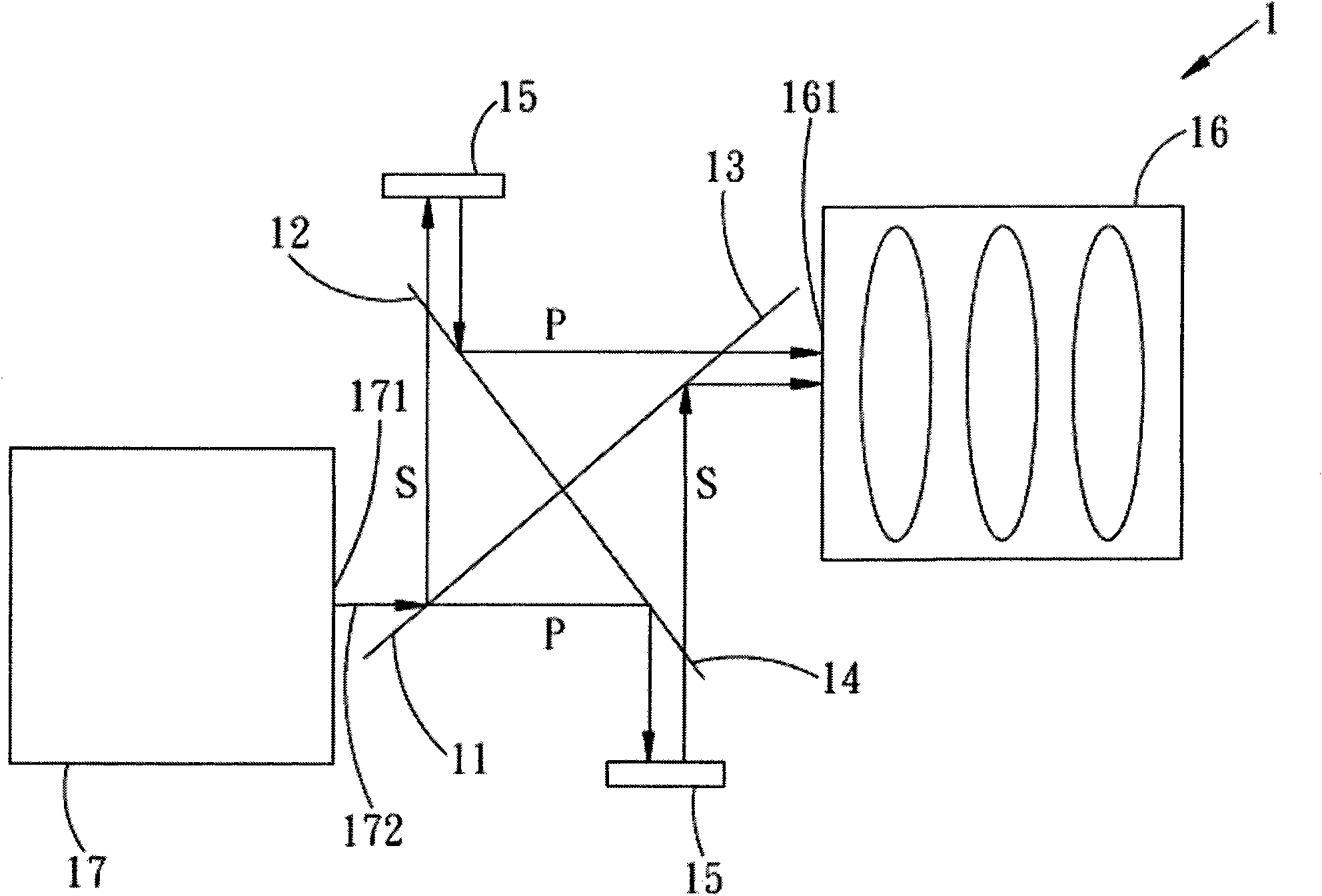
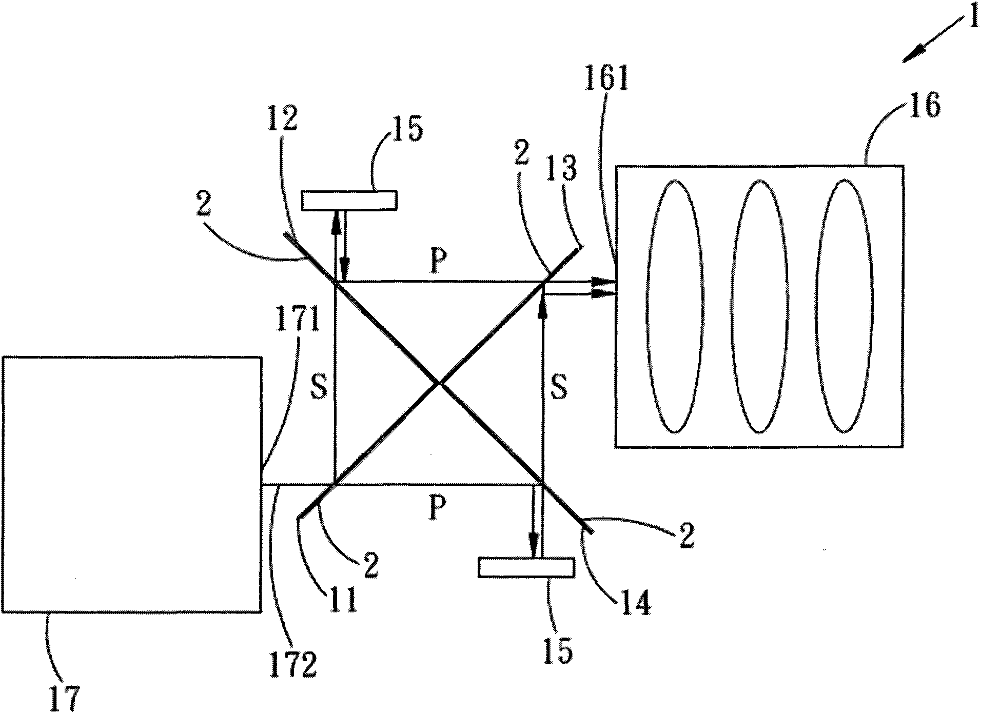
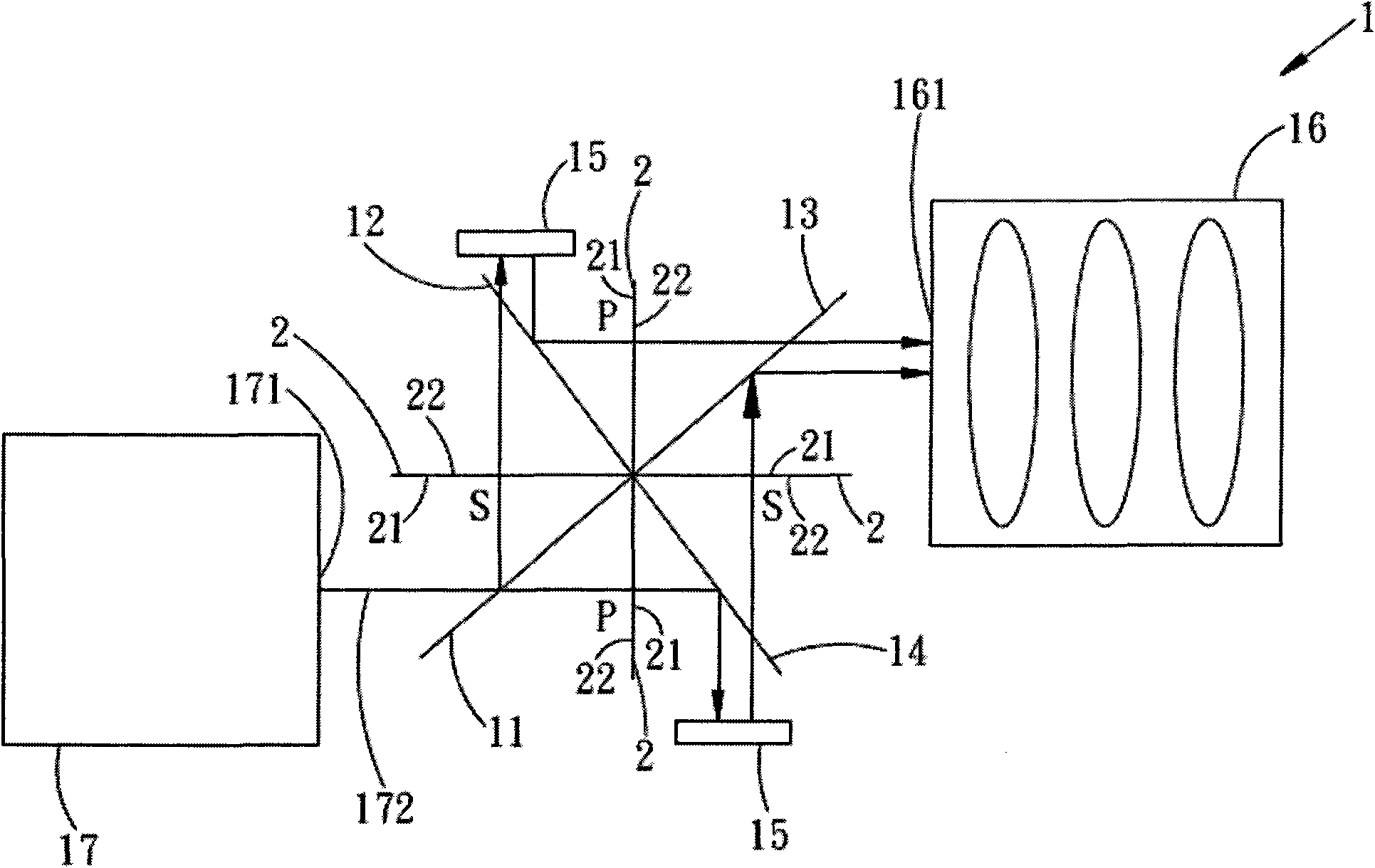
[0065] First, if figure 1 As shown, it is a schematic diagram of the first preferred embodiment of the projection device of the present invention, the projection device 1 includes a first reflective polarization beam splitting component 11, a first 90-degree reflective polarization beam splitting component 12, a second reflective A polarizing beam splitting component 13, a second 90-degree reflective polarizing beam splitting component 14, several reflective liquid crystal on silicon (LCoS; Liquid Crystal on Silicon) panels 15, a projection lens 16 and a light source 17.

[0066] The first reflective polarization splitting component 11, the first 90-degree reflective polarization splitting component 12, the second refl...


PUM


Abstract

The invention discloses a projector, which comprises a first reflective polarization beam splitter (PBS) assembly, a first vertical reflective PBS assembly, a second reflective PBS assembly, a second vertical reflective PBS assembly, a plurality of reflective silica-based liquid crystal display panels, a projection camera and a light source. The first reflective PBS assembly, the first vertical reflective PBS assembly, the second reflective PBS assembly and the second vertical reflective PBS assembly are arranged clockwise in an X shape at an interval. The projector can be matched with adsorptive polaroids; and thus, the contrast ratio of the projector is improved, interference is avoided at the internal part of the projector, and the projection quality is improved.

Description

technical field [0001] The invention relates to a projection device, in particular to a low-cost projection device that improves contrast and is less prone to interference. Background technique [0002] At present, please refer to a 3D / 2D switchable color projection device disclosed in Taiwan Invention Patent No. I237730, which uses two liquid crystal-on-silicon reflective panels and a polarization beam splitter group to output images from different viewing angles. Stereoscopic image information for projecting a stereoscopic image. [0003] After the light source irradiates the polarization beam splitter prism group, it is divided into two beams of light whose polarization directions are orthogonal to each other by the polarization beam splitter group, and then enters two silicon crystal liquid crystal reflective panels respectively, and the polarization direction is changed after being modulated by the two silicon crystal liquid crystal reflective panels. The output is the...

Claims


Application Information

Patent Timeline
Patent Type & Authority Applications(China)
IPC IPC(8): G02B27/28G02B27/10G02B5/30G03B21/00
Inventor 陈燕晟游进洲陈俊民萧舒展
Owner SHINYOPTICS
Learn More