
Wind noise detection method and system

一种风噪声、检测风的技术,应用在多麦克风系统领域,能够解决灵敏度和频率响应不符、风噪声信号可靠检测难以实现、检测风噪声等问题

Active Publication Date: 2011-11-09
INVENSENSE
View PDF8 Cites 21 Cited by
  • Summary
  • Abstract
  • Description
  • Claims
  • Application Information

AI Technical Summary

Problems solved by technology

However, reliable detection of wind noise signals has proven difficult to achieve (for example) due to their overlapping spectral or temporal content with desired signals such as music and speech signals
In a multi-microphone system, it is difficult to detect wind noise in two or more microphone signals due to mismatched sensitivities and frequency responses of the two microphones

Method used


Image

  • Wind noise detection method and system
  • Wind noise detection method and system
  • Wind noise detection method and system

Examples


Embodiment Construction

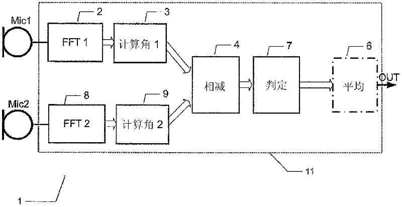
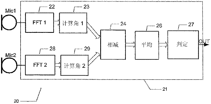
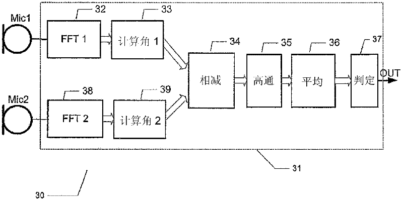
[0058] Several preferred embodiments of the present invention will be described below. To facilitate comparison of the different embodiments, corresponding parts are indicated by like reference numerals on the figures.

[0059] figure 1 is a schematic diagram of a multi-microphone system according to a first embodiment of the present invention, the multi-microphone system comprising a first microphone, Mic 1, and a second microphone denoted by Mic 2, the first and second microphones being operatively connected to on the signal processor component 11 to provide the first and second microphone signals thereto. The first and second microphone signals are preferably provided in digital form to the signal processor assembly 11, but for simplicity the A / D converter has been omitted from the figure. In practice, each microphone, Mic 1 and Mic 2, may include an integrating A / D converter to provide a digital microphone signal at a predetermined sampling frequency. Alternatively, the...


PUM


Abstract

The present invention relates to a multi-microphone system and method adapted to determine phase angle differences between a first microphone and a second microphone signal to detect presence of wind noise.

Description

technical field [0001] The present invention relates to a multi-microphone system and method for determining the phase angle difference between a first microphone and a second microphone signal to detect the presence of wind noise. Background technique [0002] Wind-induced noise signals, or wind noise, pose serious problems to sound reception in various portable electronic devices such as mobile terminals, hearing aids, earphones, recording cameras, etc. used outdoors. Wind noise is often quite annoying in dialogue and recording, where it can reduce the intelligibility of the intended speech signal by audibly masking important speech cues, and in recording, where wind noise can destroy the preservation of music recordings. authenticity. [0003] Wind noise is caused by air turbulence around surface components near the microphone inlet port of the portable electronic device. These surface features convert the steady wind flow into turbulent pressure fluctuations which are ...

Claims


Application Information

Patent Timeline
Patent Type & Authority Applications(China)
IPC IPC(8): H04R3/00H04R25/00
CPCH04R2410/07H04R3/005
Inventor 基姆・施佩茨勒・彼得森托马斯・克罗格・斯托尔茨
Owner INVENSENSE
Learn More