
Sandblasting position controlling device

A control device and a sandblasting technology, applied in the field of sandblasting machines, can solve problems such as inability to control sandblasting surfaces

Inactive Publication Date: 2011-11-16
TIANJIN ZHONGHUAN TIANJIA ELECTRONICS
View PDF4 Cites 1 Cited by
  • Summary
  • Abstract
  • Description
  • Claims
  • Application Information

AI Technical Summary

Problems solved by technology

Obviously, direct use of off-the-shelf blasting machines cannot effectively control the blasted and non-sandblasted surfaces, and a set of blasting position control devices must be made

Method used


Image

  • Sandblasting position controlling device
  • Sandblasting position controlling device
  • Sandblasting position controlling device

Examples


Embodiment Construction

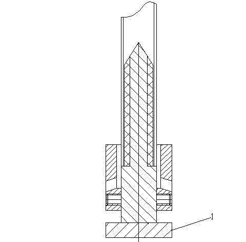
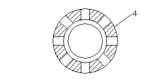
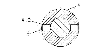
[0010] Such as figure 1 , 2 . As shown in 3, a sandblasting position control device includes a rotating mandrel 2 screwed to the rotating disk 1 of the sandblasting machine, and also includes an outer protective cover 4, which is a circular hollow body. The wall of the body is provided with several sand guide holes 4-1, and the outer protective sleeve 4 is arranged on the lower part of the rotating mandrel 2. A jackscrew hole 4-2 is provided below the sand guide hole 4-1, and two jackscrews 3 fix the outer protective sleeve 4 on the bottom of the rotating mandrel 2.

[0011] In order to protect the inner side of the workpiece, a non-metallic inner protective sleeve 6 is set on the top of the rotating mandrel 2, and the preferred material is polyurethane material.

[0012] For workpieces with different sandblasting heights, the top screw 3 can be unscrewed to adjust the height of the outer protective cover 4. Outer protective cover 4 adopts non-metallic material, and preferr...


PUM


Abstract

The invention relates to a sandblasting machine, especially to a sandblasting position controlling device in the sandblasting machine. The sandblasting position controlling device comprises a rotating mandrel which forms a bolt connection with a rotating disc of the sandblasting machine, inclusive of an outer protection sleeve which is a circular hollow body, wherein a plurality of sand-guiding holes are disposed on the wall of the hollow body and the outer protection sleeve is arranged at the bottom of the rotating mandrel. With the combination of the sandblasting position controlling device and the sandblasting machine, when tubular workpieces are sandblasted, the workpieces inside the outer protection sleeve can be guaranteed not to be sandblasted, and sandblasting areas can be easily controlled, thus creating a clear boundary between the sandblasted part and the part which is not sandblasted.

Description

technical field [0001] The invention relates to a sandblasting machine, in particular to a sandblasting position control device in the sandblasting machine. Background technique [0002] At present, the performance of the sandblasting system of sandblasting machines produced by various manufacturers has reached a very high level, but there has not been much research on the control of the sandblasting position, and in the actual sandblasting process, many workpieces are not Sandblasting is required. In the office consumables industry, sandblasting has become an indispensable processing method in the production of developing sleeves. For sandblasting of developing sleeves, a certain length of unsandblasted smooth surface must be left at both ends. There also needs to be clear demarcation lines between sand sections. Obviously, the direct use of ready-made sandblasting machines cannot effectively control the sandblasting surface and the non-sandblasting surface, and a set of ...

Claims


Application Information

Patent Timeline
Patent Type & Authority Applications(China)
IPC IPC(8): B24C9/00
Inventor 姜真钟秀华韩立胜张明熠
Owner TIANJIN ZHONGHUAN TIANJIA ELECTRONICS
Learn More