Method for correcting system error during splicing sub-aperture

A technology of sub-aperture stitching and systematic error, which is applied in the field of optical measurement, can solve the problems of rising stitching error, complicated method, and no correction of systematic error, so as to achieve the effect of improving accuracy, enhancing robustness, and reducing the influence of systematic error

Inactive Publication Date: 2011-11-16
NANJING UNIV OF SCI & TECH
View PDF4 Cites 13 Cited by
  • Summary
  • Abstract
  • Description
  • Claims
  • Application Information

AI Technical Summary

Problems solved by technology

[0003] However, in the surface shape measurement, each sub-aperture is measured relative to the digital wave surface interferometer, so the error of the reference flat crystal will inevitably enter the test data, and as a system error, the splicing error will increase greatly
This systematic error cannot be solved by using various existing splicing error averaging algorithms, and additional tests must be used to calibrate and correct
Correcting the system error requires the absolute inspection of the reference flat surface shape. The current absolute inspection method for the full shape is complicated and closely related to the measurement environment conditions and the state of the interferometer. The obtained reference flat surface shape data is not robust and cannot It is used as a benchmark result for long-term use, and it cannot be used in the measurement process of another interferometer (such as a sub-aperture scanning interferometer) with the reference flat crystal, which makes it impossible to propose a better method for correcting system errors so far.

Method used


Image

  • Method for correcting system error during splicing sub-aperture
  • Method for correcting system error during splicing sub-aperture
  • Method for correcting system error during splicing sub-aperture

Examples


Embodiment Construction

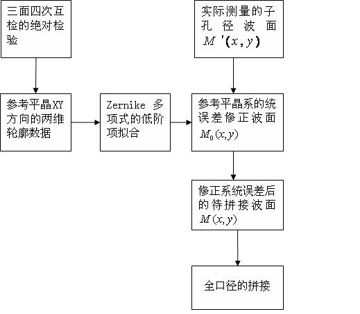
[0018] The invention is mainly used to solve the system error caused by the shape error of the reference flat crystal when the sub-aperture splicing method is used to detect the large-diameter optical mirror surface and the problem of the amplification of the system error. combine figure 1 , the present invention is a method for correcting systematic errors in sub-aperture stitching, comprising the following steps:

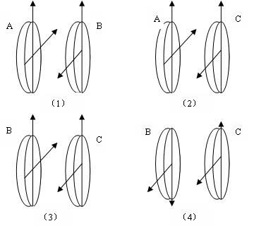
[0019] Step 1. Use the three-sided four-time mutual inspection method to carry out the absolute inspection of the surface shape of the reference flat crystal, thereby obtaining the line profile data of the reference flat crystal in two vertical directions passing through its center; preferably using two auxiliary flat crystals to perform three-sided four-sided inspection. Absolute checks for mutual checks.

[0020] Such as figure 2 As shown, two auxiliary flat crystals B and C are used to perform absolute inspection of three sides and four mutual inspections on...


PUM


Abstract

The invention discloses a method for correcting a system error during splicing sub-aperture. The method comprises the following steps of: acquiring a two-dimensional profile curve of a reference optical flat on a splicing shaft by utilizing absolute plane inspection participated by an auxiliary optical flat; constructing a surface shape error correction wave surface of the reference optical flat by utilizing data of the profile curve; and performing real-time correction during measurement of the sub-aperture. By the method, the influence of a surface shape error of the reference optical flat on the solving of an inclined coefficient during splicing the sub-aperture can be reduced to the greatest extent, and the precision of a splicing wave surface is effectively improved.

Description

technical field [0001] The invention belongs to the field of optical measurement, in particular to a method for correcting systematic errors in sub-aperture splicing. Background technique [0002] In the splicing measurement of the surface shape of large-scale optical components, each sub-aperture is adjusted and measured independently, so different inclinations will be introduced. Stitching is to accurately position the sub-apertures and eliminate the difference in inclination. The most commonly used splicing method is the overlapping sub-aperture method, which uses the overlapping area between adjacent sub-apertures to calculate their relative inclination and eliminate it. In this process, the random error of interferometer measurement, sampling lattice misalignment error, sub-aperture positioning error, etc. caused by environmental factors usually appear as the residual error of closed sub-aperture cycle splicing, for which there are many error averaging algorithms was p...

Claims


Application Information

Patent Timeline
Patent Type & Authority Applications(China)
IPC IPC(8): G01B11/24
Inventor 王青徐新华陈磊周游
Owner NANJING UNIV OF SCI & TECH
Why Eureka
Try Eureka