Cathode wire structure for magnetron

A cathode wire and magnetron technology, applied in the field of magnetrons, can solve the problems of harsh selection of raw materials for connecting pieces, high metal material costs, increased production costs, etc. Effect

Inactive Publication Date: 2011-11-16
LG ELECTRONICS (TIANJIN) APPLIANCES CO LTD
View PDF3 Cites 3 Cited by
  • Summary
  • Abstract
  • Description
  • Claims
  • Application Information

AI Technical Summary

Problems solved by technology

[0017] In the cathode wire structure of the magnetron, a through hole connecting the central guide rod and the side guide rod is set on the connecting piece, and the central guide rod and the side guide rod pass through the through hole of the connecting piece to be fixed, and at the same time, a depression is set on the connecting piece by punching The blind hole 38, the cathode lead wire is inserted into the blind hole, so that the connection piece and the cathode lead wire are connected and fixed through cooperation. Since the processing of the blind hole requires the connection piece to have good ductility, the raw material selection of the connection piece is relatively harsh. High ductility metal materials are expensive, and at the same time, the processing of blind holes is relatively difficult, and the production cost has also increased

Method used


Image

  • Cathode wire structure for magnetron
  • Cathode wire structure for magnetron
  • Cathode wire structure for magnetron

Examples


Embodiment Construction

[0033] The present invention will be described in detail below in conjunction with the accompanying drawings and embodiments.

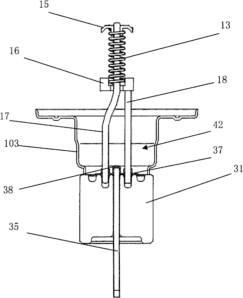
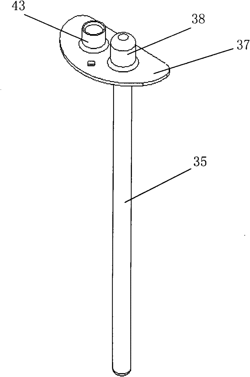
[0034] Figure 5 It is a schematic diagram when the cathode lead-out wire and the connecting piece are fixed to each other in the cathode wire structure of the magnetron of the present invention; Figure 6 It is a schematic diagram of the connecting piece in the cathode wire structure of the magnetron in the present invention; Figure 7 It is a schematic diagram of the cathode lead-out wire in the cathode wire structure of the magnetron in the present invention.

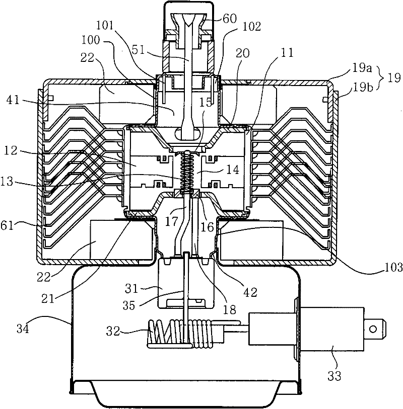
[0035] like Figure 5 to Figure 7As shown, the cathode cover of the magnetron is arranged at the lower part of the lower magnetic pole of the magnetron, and is sealed and connected with the anode shell of the magnetron to form a lower sealed chamber. The metal cathode cover and the anode shell are tightly connected by welding, and the cathode seal The middle position of the lower part of ...


PUM


Abstract

The invention provides a cathode wire structure for a magnetron. The structure comprises a center guide rod, a side guide rod, a ceramic component and a connecting piece, wherein a fixed through hole is arranged on the connecting piece, the upper end of a cathode lead passes through the fixed through hole and is matched and fixed with the connecting piece. In order to ensure the soundness between the cathode lead and the connecting piece and determine the fixed position between the cathode lead and the connecting piece, a boss or a frustum with a diameter the same as that of the fixed through hole is arranged on the upper end of the cathode lead, and the upper end of the cathode lead can be inserted into the fixed through hole through the boss and the frustum and then fixed by virtue of welding. On one hand, the processing of the connecting piece is simpler and the fixed through hole can be formed by punching; and on the other hand, the material requirement of the connecting piece can be relatively lowered, i.e., the material cost of the connecting piece can be reduced.

Description

technical field [0001] The invention belongs to the technical field of magnetrons, and in particular relates to a cathode lead wire structure of a magnetron which is provided with a fixed through hole on a connecting piece, and a cathode lead wire is directly inserted into the fixed through hole, thereby improving the processing technology and production efficiency. Background technique [0002] figure 1 It is a longitudinal sectional view of a magnetron structure in the prior art; figure 2 is a cross-sectional view of the cathode wire structure of the magnetron in the prior art; image 3 It is a schematic diagram when the cathode lead wire and the connecting piece are fixed to each other in the cathode wire structure of the magnetron in the prior art; Figure 4 It is a schematic diagram of the connecting piece in the cathode wire structure of the magnetron in the prior art. [0003] like Figure 1 to Figure 4 As shown, the magnetron mainly includes: a positive electrod...

Claims


Application Information

Patent Timeline
Patent Type & Authority Applications(China)
IPC IPC(8): H01J23/05
Inventor 尹燕
Owner LG ELECTRONICS (TIANJIN) APPLIANCES CO LTD
Why Eureka
Try Eureka