Reducible relief opening

A kind of impeller pump, working technology, applied in the components of the pumping device for elastic fluid, pump control, non-variable pump, etc., can solve the problem of slip ring seal damage, etc., and achieve the effect of reliable mode

Inactive Publication Date: 2011-11-16
KSB AG
View PDF6 Cites 3 Cited by
  • Summary
  • Abstract
  • Description
  • Claims
  • Application Information

AI Technical Summary

Problems solved by technology

Otherwise there is a danger, for example, of operating-induced pressure changes, which, due to too low a pressure, open the seal in the sealing chamber and thus damage the slip ring due to the introduction of external air and the resulting dry running on the slip ring seal. seal damage

Method used


Image

  • Reducible relief opening
  • Reducible relief opening
  • Reducible relief opening

Examples


Embodiment Construction

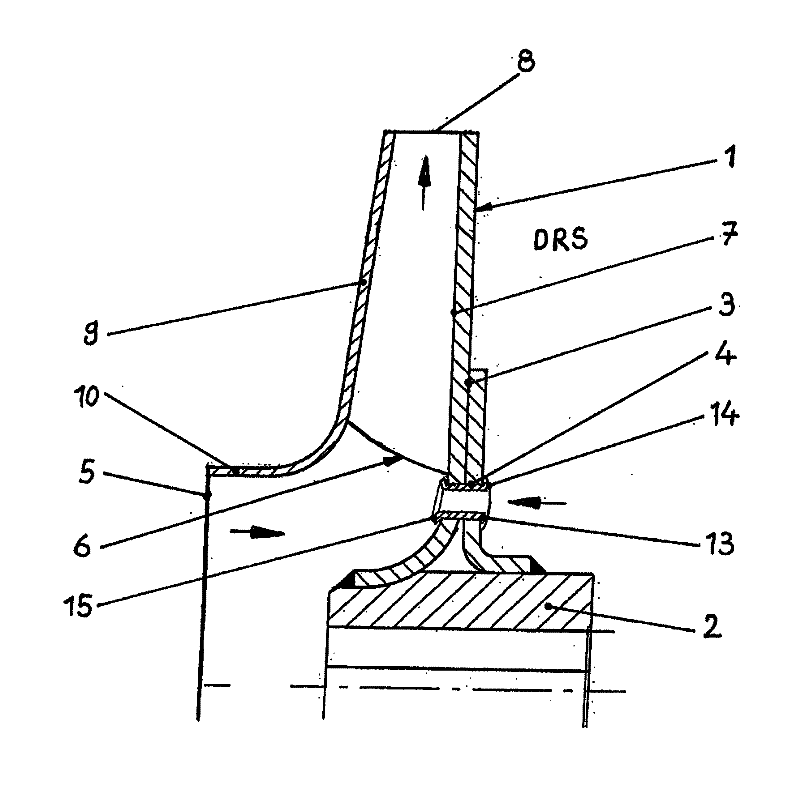
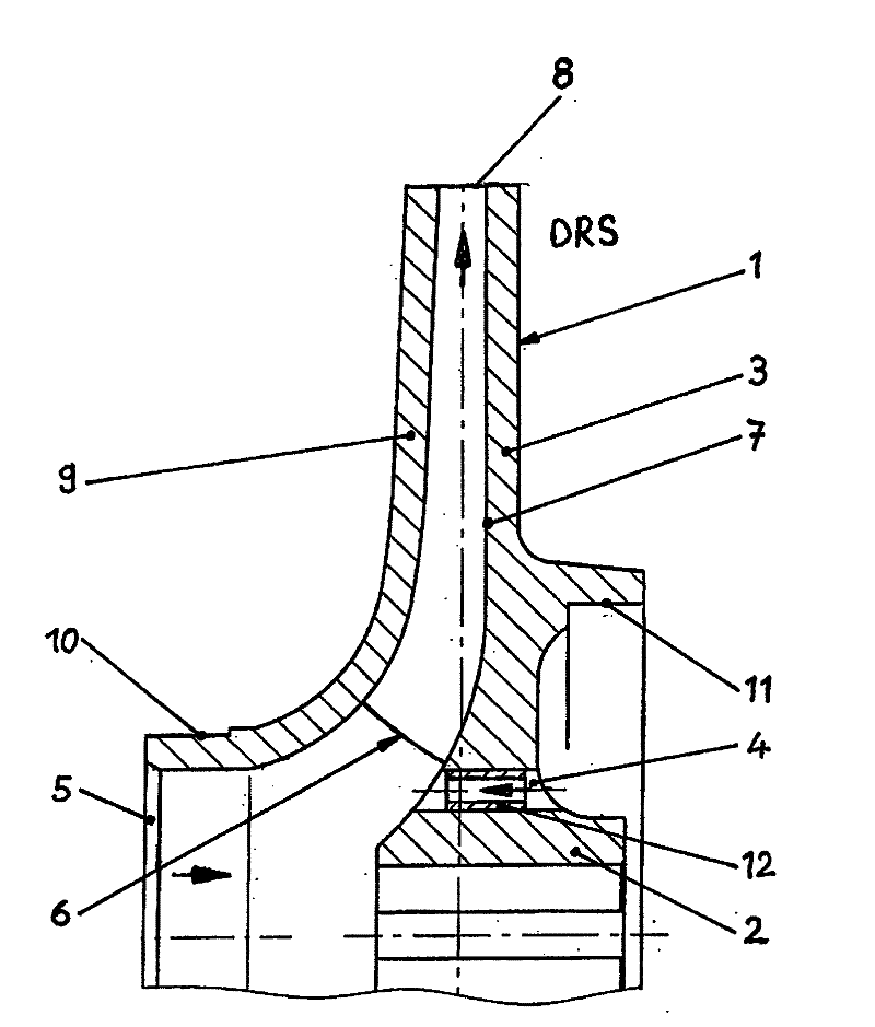
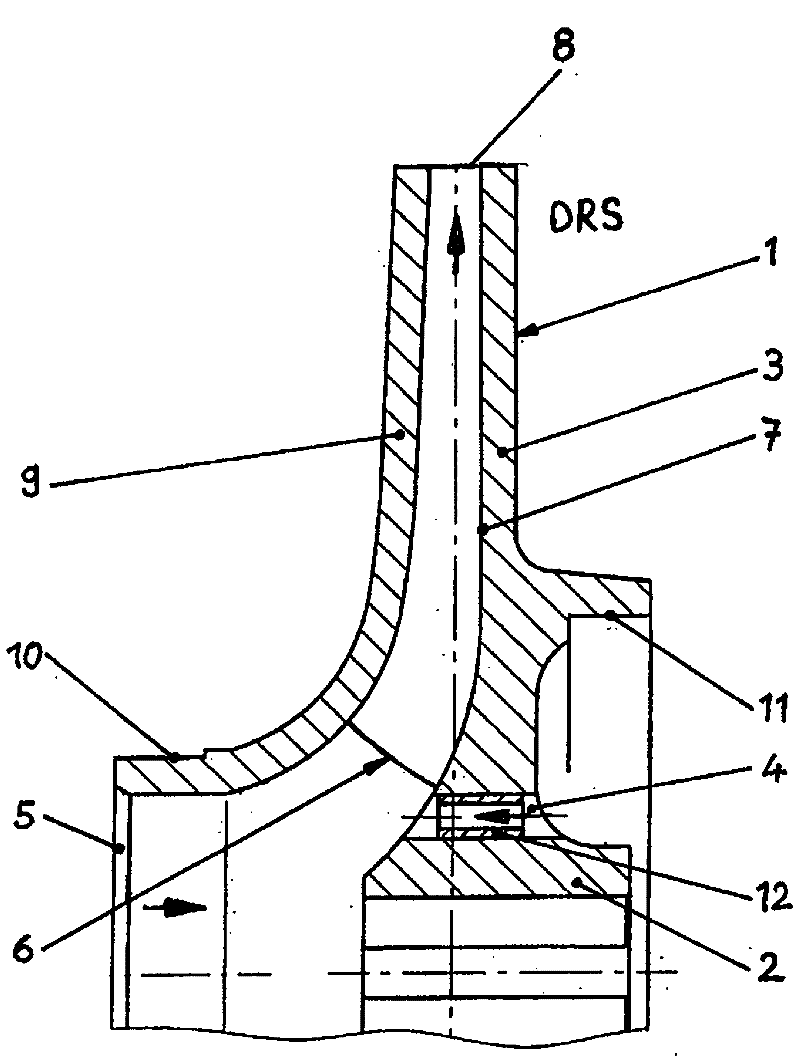
[0013] figure 1 A vane pump impeller is shown in radial and closed construction. The housing housing the impeller 1 as well as the shaft driving the impeller 1 via the hub 2 and the shaft seal are not shown for greater clarity. The rotor wheel 1 made of a cast part has a pressure-side rotor cover plate 3 which, at the transition to the hub 2, is equipped with a plurality of diametrically distributed relief openings 4 . They often consist of holes.

[0014] The fluid delivered from the impeller 1 flows from the impeller inlet 5 through the vane channels 7 delimited by the vanes 6 to the impeller outlet 8 and is discharged into the interior of the housing. The pressure inside the housing at the impeller outlet 8 acts and exerts a force in the axial direction both on the pressure-side impeller cover plate and on the opposite suction-side impeller cover plate 9 . Due to the different sizes of the working impeller cover disk area, a derived axial force is generated by the pressu...


PUM


Abstract

The invention relates to a reducible relief opening. A single or multi-stage centrifugal pump has a driven impeller (1) or impellers disposed in the pump housing and a shaft seal. The impeller has one or more adjustable relief openings (4) in at least one cover disc (3). One or more sleeve-like inserts (12, 13) are disposed in one or more relief openings (4).

Description

technical field [0001] The invention relates to a single-stage or multi-stage impeller pump with driven impellers arranged inside the pump casing, shaft seals, wherein one or more movable impellers are arranged on at least one cover plate of at least one impeller Adjusted unloading hole. Background technique [0002] In the impeller pump, the resultant force of the axial force acting on the working impeller of the pump is called the axial thrust. The accurate determination of the axial thrust is described in the third volume of the impeller pump dictionary with the subject word "axial thrust" on page 32 and the next page. In single-stage impeller pumps, axial relief via relief bores in the pressure-side rotor cover disk has proven to be a frequently used measure. The arrangement of the discharge openings is also realized in combination with additional sealing gaps and housing ribs or rotor blades. [0003] It is difficult to calculate the flow cross-section of such unload...

Claims


Application Information

Patent Timeline
Patent Type & Authority Applications(China)
IPC IPC(8): F04D15/00F04D29/22F04D29/02
CPCF04D15/0027F04D29/026F04D29/2266F05D2300/501F05D2300/518
Inventor A.克劳斯
Owner KSB AG
Why Eureka
Try Eureka