Attenuator for damping pressure fluctuations in a hydraulic system

A hydraulic system and attenuator technology, applied in the direction of fluid pressure actuation devices, fluid pressure actuation system components, engine components, etc., can solve the problems of hydraulic system cavitation, harmful overpressure or underpressure pulse, etc. corrosion, reduce overvoltage and undervoltage pulses, improve the effect of operation

Active Publication Date: 2014-07-30
WARTSILA FINLAND OY
View PDF6 Cites 0 Cited by
  • Summary
  • Abstract
  • Description
  • Claims
  • Application Information

AI Technical Summary

Problems solved by technology

This tends to introduce unwanted over or under pressure pulses and even cause cavitation in the hydraulic system

Method used


Image

  • Attenuator for damping pressure fluctuations in a hydraulic system
  • Attenuator for damping pressure fluctuations in a hydraulic system
  • Attenuator for damping pressure fluctuations in a hydraulic system

Examples


Embodiment Construction

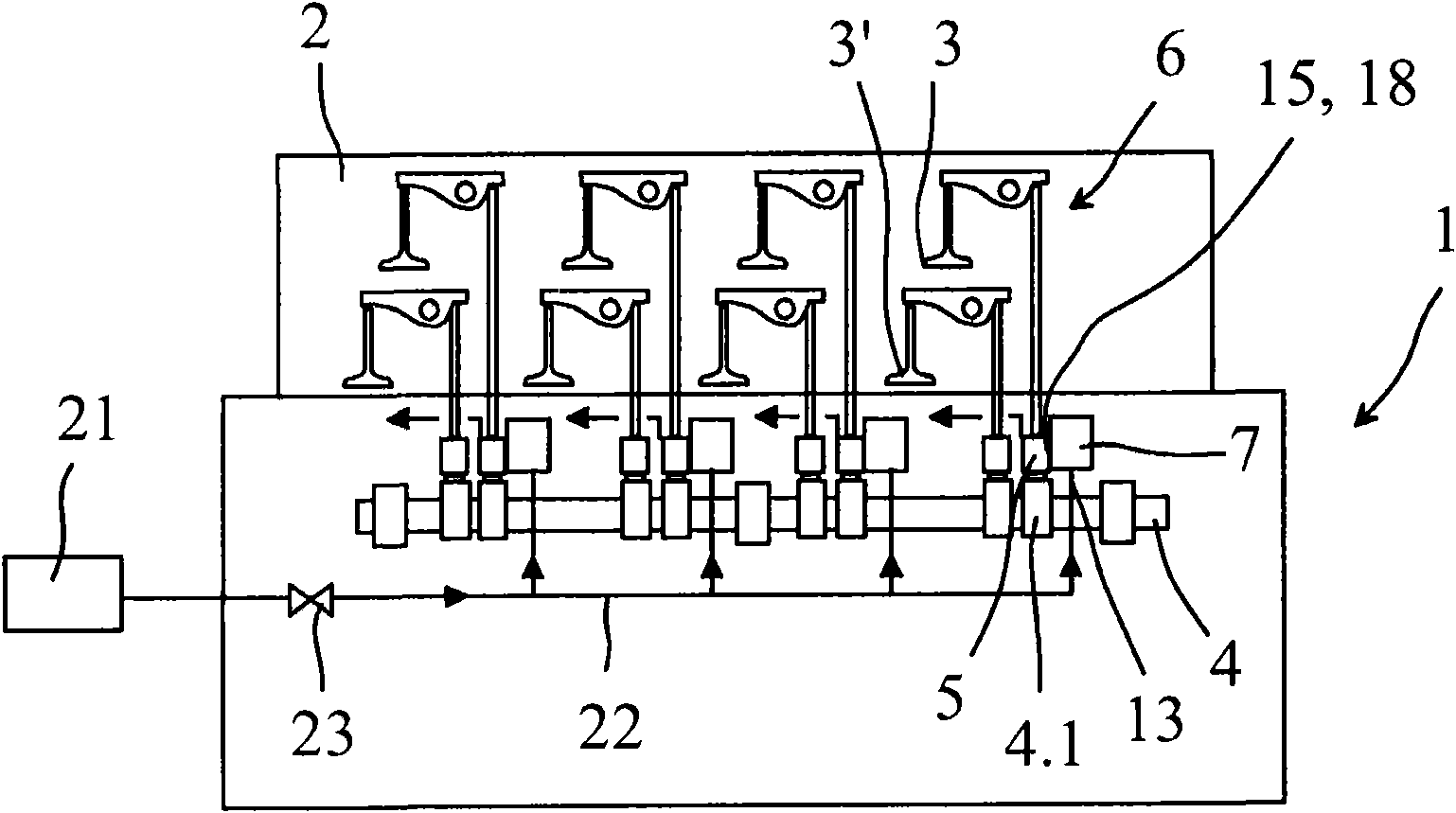
[0013] attached figure 1 A piston engine 1 is shown schematically, the gas exchange of the engine's cylinders (not shown) being directed by intake and exhaust valves 3, 3' located on the cylinder block 2. The valve 3 is operated by a valve train 6, receiving its operating force from the camshaft 4 of the engine, generally guided by the cam profile 4.1. The force transmission connection between each valve mechanism 6 is realized by a hydraulic control system or guide 5 .

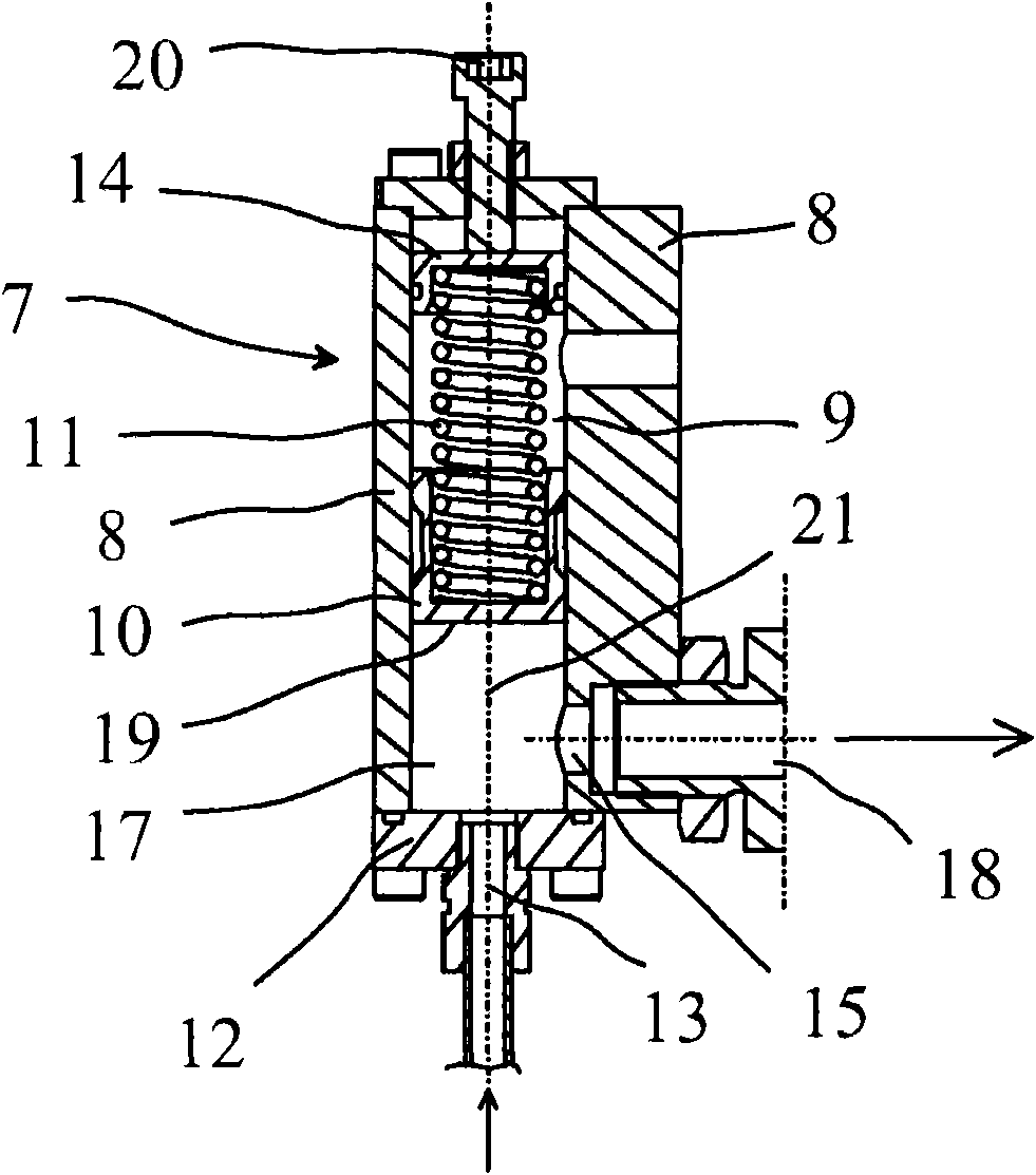
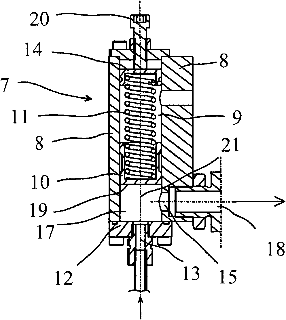
[0014] By means of the guide 5, the timing of the valves 3, 3', i.e. the moment of opening and closing during the working cycle of the cylinder, can be varied as desired. The guide 5 can be implemented in various ways. In one embodiment, the guide 5 comprises a space for hydraulic fluid, which is connected to the hydraulic system via a supply channel 18 . The space surrounds the piston, which is in force-transmitting connection with the cams and the valve mechanism of the camshaft of the engine. By varyin...


PUM


Abstract

An attenuator (7) for damping pressure fluctuations in a hydraulic system, which attenuator comprises a body (8) with a chamber (9), in which a movable piston (10) loaded by a spring (11 ) is adapted, a fluid space (17) inside the chamber (9), which space is delimited by the piston surface (19) of the piston (10), an inlet conduit (13) for feeding hydraulic fluid into the fluid space (17) and an outlet conduit (15) for discharging hydraulic fluid from the fluid space (17). The flow resistance in the inlet conduit (13) is higher than the flow resistance in the outlet conduit (15).

Description

technical field [0001] The present invention relates to an attenuator for damping pressure fluctuations occurring in a hydraulic system. Background technique [0002] For example, hydraulic systems and components are provided for piston engines where the demand for hydraulic fluid varies strongly over time. For example, in a control system for an intake valve equipped with alternate timing, the timing of the intake valve is varied by adjusting the flow rate of hydraulic fluid into the control system. The volume flow of the hydraulic fluid required by the control system is varied in pulses, and the flow changes occur rapidly and with high frequency. This tends to introduce unwanted over- or under-pressure pulses and even cavitation in the hydraulic system. Contents of the invention [0003] The object of the present invention is to provide an attenuator by means of which pressure fluctuations in a hydraulic system can be compensated. [0004] The object of the invention ...

Claims


Application Information

Patent Timeline
Patent Type & Authority Patents(China)
IPC IPC(8): F15B1/02F16L55/04F01L13/00
CPCF15B2201/413F01L1/3442F01L13/0015F15B2201/31F15B2201/21F01L13/0005F01L2001/34426F15B21/008F01L2001/2444F15B1/021F15B1/04F16L55/04F15B1/02F01L13/00
Inventor M·桑德斯滕
Owner WARTSILA FINLAND OY
Why Eureka
Try Eureka