Greenhouse heater

A heat booster and governor technology, applied in the heating field, can solve the problems of slow temperature rise and insufficient fuel utilization, and achieve the effects of full fuel combustion, no harmful gas, and fast heating speed

Inactive Publication Date: 2011-11-23
宁洪存
View PDF0 Cites 0 Cited by
  • Summary
  • Abstract
  • Description
  • Claims
  • Application Information

AI Technical Summary

Problems solved by technology

The greenhouse warming equipment on the market often has disadvanta

Method used


Image

  • Greenhouse heater
  • Greenhouse heater

Examples


Embodiment Construction

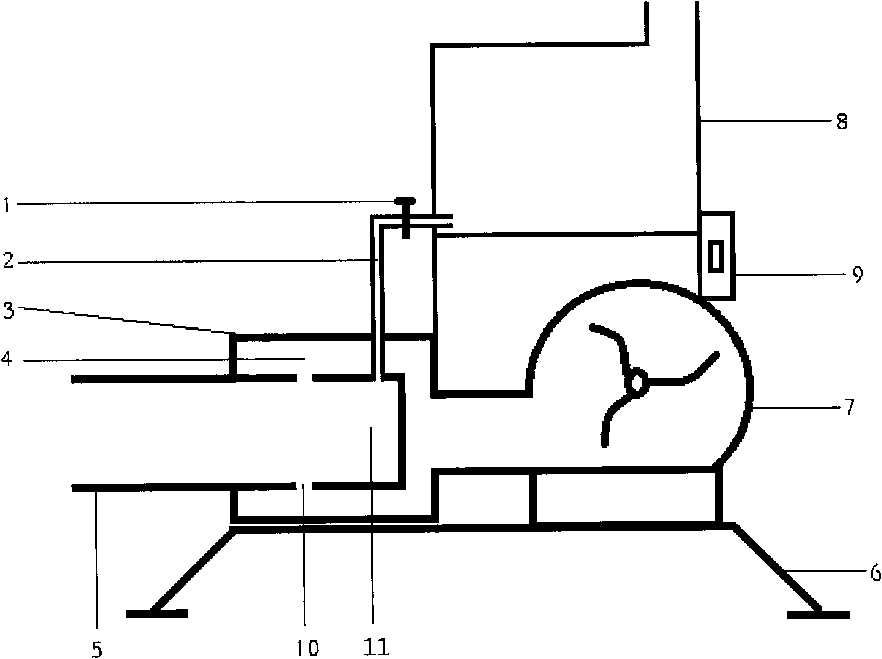
[0009] As shown in the figure, the fuel tank 8 is connected to the oil passage 2, and a switch 1 is provided between the two. The oil passage 2 is connected to the combustion chamber 11, and the air passage 4 and the combustion chamber 11 are connected through a circle of air inlets 10, and the combustion chamber 11 The end is provided with a fire outlet 5, the air duct 4 communicates with the fan 7, and the fan 7 is provided with a speed regulator 9, and the bottom is a bracket 6.

[0010] The present invention mainly uses alcohol as fuel, turn on the switch 1, and at the same time ignite the paper and put it into the combustion chamber 11, turn on the fan 7, adjust the switch 1 to adjust the fuel injection rate, and adjust the governor 9 to adjust the wind speed of the fan 7 to When the alcohol reaches its best burning state, the heating process starts. Greenhouse warmer.


PUM


Abstract

The invention provides a greenhouse heater which can be used to fast heat a greenhouse, fully utilize the fuel and effectively reduce the waste. The invention is realized as follows: a fuel tank is connected with an oil channel, a switch is arranged between the fuel tank and the oil channel, the oil channel is connected with a combustion chamber, an air channel is connected with the combustion chamber through a circle of air inlets, the tail end of the combustion chamber is provided with a flame outlet, the air channel is communicated with a fan, the fan is provided with a governor, and the bottom of the fan is provided with a support. The heating speed of the heater is high; and the heater can provide CO2 for crop; and the fuel can be fullly combusted and no harmful gas is generated.

Description

Technical field [0001] The invention relates to the field of heating, in particular to a greenhouse warmer. Background technique [0002] Greenhouses play a very important role in agricultural production, and the maintenance of the temperature in the greenhouse is particularly important. The greenhouse heating equipment on the market often has the disadvantages of slow heating and insufficient fuel utilization. Summary of the invention [0003] The invention provides a greenhouse warmer, which can quickly heat the greenhouse, fully utilize fuel, and effectively reduce waste. [0004] The present invention is realized as follows: the fuel tank is connected with the oil passage, a switch is provided between the two, the oil passage is connected with the combustion chamber, the air passage is connected with the combustion chamber through a circle of air inlets, the end of the combustion chamber is provided with a fire outlet. The tunnel is connected to the fan, and a speed regulator ...

Claims


Application Information

Patent Timeline
IPC IPC(8): A01G9/24
CPCY02A40/25
Inventor 宁洪存郑进友徐星
Owner 宁洪存
Why Eureka
Try Eureka