
Method for bending rear crossbeam of heavy truck and bending die

A rear beam and bending technology, applied in the field of vehicle parts processing methods and molds, can solve the problems of difficult to control rebound, different rebound sizes of the two wing surfaces, affecting the frame assembly rhythm and the quality of the whole vehicle, etc., to reduce the difficulty of debugging, The effect of improving the quality of the vehicle

Active Publication Date: 2014-03-12
SINO TRUK JINAN POWER
View PDF7 Cites 0 Cited by
  • Summary
  • Abstract
  • Description
  • Claims
  • Application Information

AI Technical Summary

Problems solved by technology

Since the rear beam is an irregular U-shaped piece, the force on the two airfoils is asymmetrical, resulting in different springbacks on the two airfoils, difficult mold debugging, difficult and severe springback, which affects the assembly cycle of the frame and the quality of the vehicle

Method used


Image

  • Method for bending rear crossbeam of heavy truck and bending die
  • Method for bending rear crossbeam of heavy truck and bending die

Examples


Embodiment Construction

[0016] The present invention will be further described below in conjunction with the accompanying drawings and embodiments.

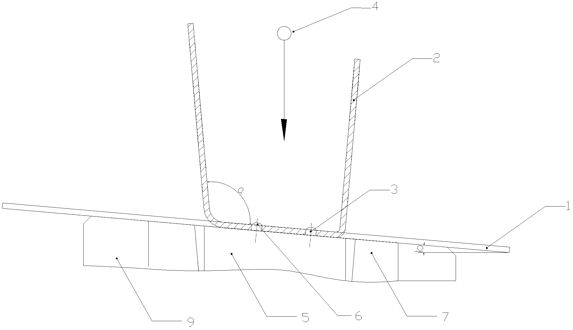
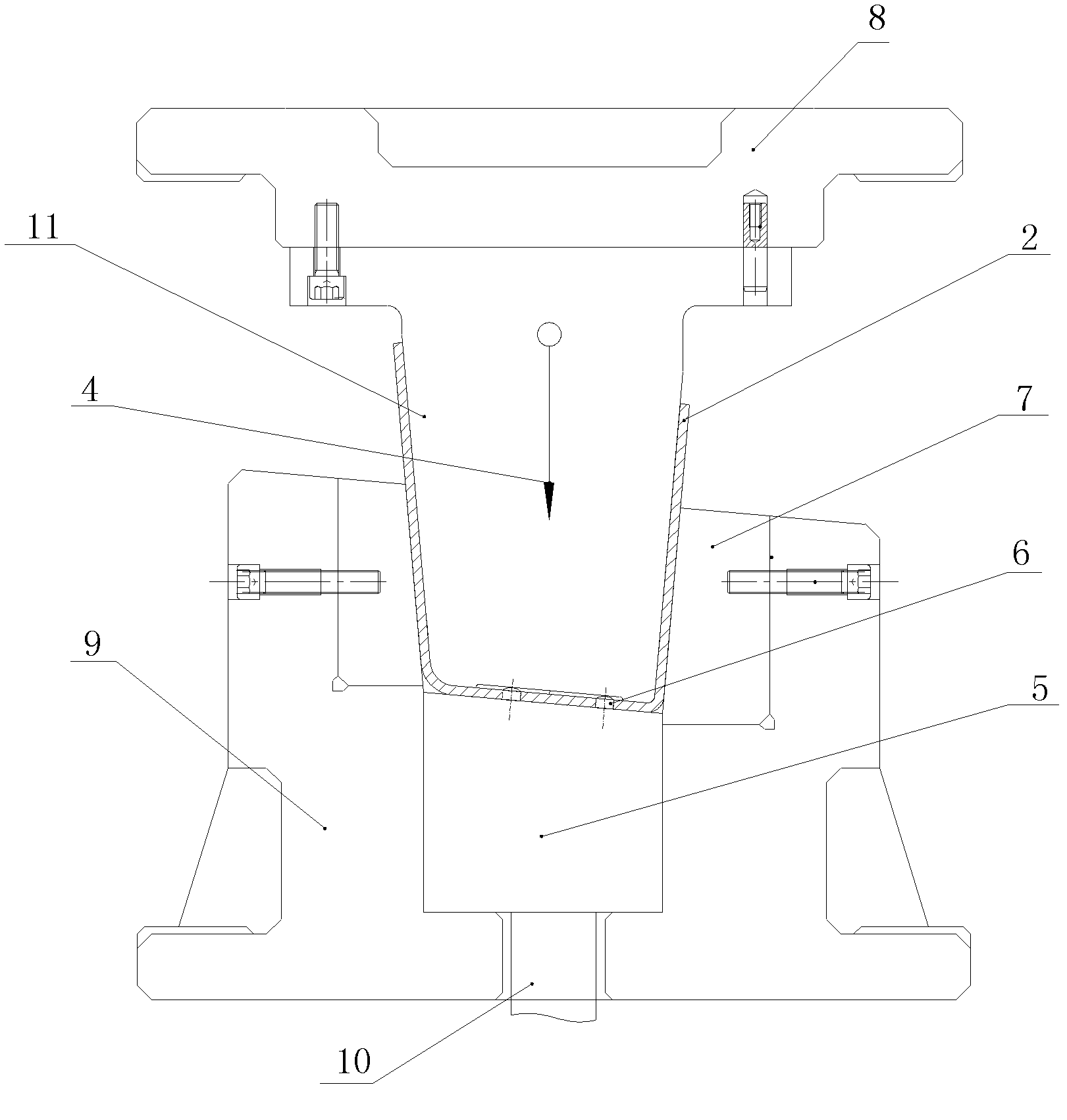
[0017] Such as figure 1 , figure 2 As shown, a bending method of the rear beam of a heavy truck includes the following steps:

[0018] 1). Install the qualified bending mold on the press;

[0019] 2). The two positioning holes 3 on the blank 1 of the falling punch are penetrated into the two positioning pins 6 provided on the upper surface of the ejector 5, and placed on the ejector 5 of the lower die 9 of the bending die; the blank 1. Place it on the top piece 5 of the bending mold at an angle of b degrees with the horizontal plane, where b=(a-90°) / 2, a is an angle greater than 90° between an airfoil of the rear beam and the bottom surface;

[0020] 4). Press the working button of the press, the punch 11 of the bending mold goes down with the slider of the press, the bending force acts on the blank 1 in a direction perpendicular to the horizontal p...


PUM

PropertyMeasurementUnit
thicknessaaaaaaaaaa

Abstract

The invention relates to a method for bending a rear crossbeam of a heavy truck. The method comprises the following steps that: a bending die which is debugged to be qualified is arranged on a press; two positioning holes on a punched blank pass through two positioning pins on the upper surface of an ejector so that the blank is placed on the ejector of a lower die of the bending die; and a working pushbutton of the press is pressed so that a male die of the bending die moves downward along with a sliding block of the press, the bending force acts on the blank in a direction vertical to the horizontal plane, and the blank is pressed by the bending force and the ejector of the bending die so as to move downward and enter a cavity of a female die of the bending die, the sliding block of the press moves downward to the bottom of the female die of the bending die, the blank is formed in the female die of the bending die, the sliding block of the press moves upward, the ejector of the bending die, a bent part and the male die of the bending die synchronously move upward to the position before bending, the male die of the bending die and the bent part are separated, and the wing surface and the bottom surface of the rear crossbeam are in an ideal state due to the rebound of a steel plate. Meanwhile, the invention also discloses the bending die matched with the method.

Description

technical field [0001] The invention relates to a vehicle component processing method and a mold, in particular to a bending method and a bending mold for a rear beam of a heavy truck. Background technique [0002] The rear beam of a heavy-duty tractor requires an irregular U-shaped piece with an angle between one wing surface and the bottom surface of 90°, and the angle a between the other wing surface and the bottom surface is greater than 90°. The height of the two wing surfaces is greater than 250mm. The steel plate used for the girder has a material thickness of 6 to 10 mm. The usual bending method is: the bending blank is placed horizontally on the top part of the bending mold. When bending, the bending force is perpendicular to the bottom surface of the beam. Since the rear beam is an irregular U-shaped piece, the force on the two airfoils is asymmetrical, resulting in different springbacks on the two airfoils, difficult mold debugging, and difficult and serious sprin...

Claims


Application Information

Patent Timeline
Patent Type & Authority Patents(China)
IPC IPC(8): B21D7/06B21D37/10
Inventor 和爱华王鹏刚
Owner SINO TRUK JINAN POWER
Learn More