Helical blade drawing device

A technology of spiral blades and blades, which is applied in the field of conveying machinery manufacturing, can solve problems such as high cost, low equipment utilization rate, and large investment, and achieve the effects of convenient use, reduced labor intensity, and low cost

Inactive Publication Date: 2011-11-23
李正峰
View PDF4 Cites 6 Cited by
  • Summary
  • Abstract
  • Description
  • Claims
  • Application Information

AI Technical Summary

Problems solved by technology

However, some small and medium-sized manufacturers purchase equipment such as presses and molds, and there are problems such as large investment and low equipment utilization.
It is often expensive for users to replace worn spiral blades if they buy them from the manufacturer

Method used


Image

  • Helical blade drawing device
  • Helical blade drawing device
  • Helical blade drawing device

Examples


Embodiment Construction

[0017] The accompanying drawing discloses a non-restrictive structural schematic diagram of a preferred embodiment involved in the present invention, and the technical solution of the present invention will be described in detail below in conjunction with the accompanying drawings.

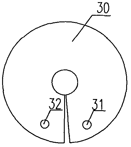
[0018] Such as image 3 As shown, a fixing process hole 31 and a stretching process hole 32 are drilled on the helical blade blank 30 to be drawn.

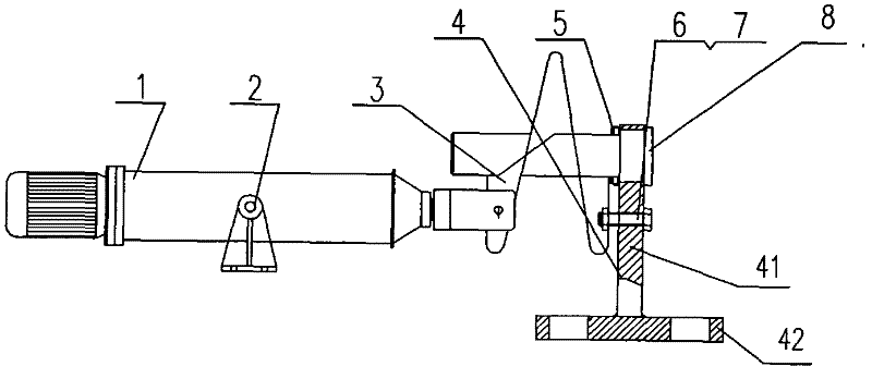
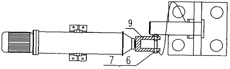
[0019] Such as figure 1 and figure 2 As shown, a spiral blade drawing device according to the present invention includes a frame and a mandrel. The frame 4 includes a bottom plate 42 and a support plate 41 fixedly connected to the bottom plate. The mandrel 8 is vertically installed on the support plate 41, the pulling braking power device is located on the same side of the mandrel 8, the extending end of the pulling braking power device is provided with a blade stretching installation part, and the side of the support plate 41 located at the lower ...


PUM

PropertyMeasurementUnit
diameteraaaaaaaaaa

Abstract

The invention relates to a helical blade drawing device, comprising a rack and a spindle, wherein the rack comprises a base plate and a support plate fixedly connected with the base plate, the spindle is vertically arranged at one side of the support plate, the drawing power device and the spindle are arranged at the same side of the spindle, the extending end of the drawing power device is provided with a blade drawing mounting part, and a blade fixing mounting part is arranged at one side of the support plate arranged at the lower part of the spindle. In the invention, an electric hydraulic push rod is taken as the drawing power device, labour intensity of workers is reduced, and working efficiency is improved; helical blades with different diameters can be drawn by adjusting tension and replacing the spindle; and the helical blades with different thread pitches can be drawn by regulating stroke in a rated stroke range, thus the aim that the helical blade drawing device provided by the invention serves multiple purposes is achieved. The helical blade drawing device provided by the invention has the characteristics of simple structure, convenience in application and low cost.

Description

technical field [0001] The invention relates to a screw conveyor blade manufacturing device, in particular to a screw blade drawing device, which belongs to the field of conveying machinery manufacturing. Background technique [0002] Screw conveyor is the main equipment for conveying powdery materials in cement, grain, chemical and other industries. It is widely used and runs for a long time. The screw blades are easy to wear and are the wearing parts on the screw conveyor. Specialized manufacturers mainly use special forming molds and press molding to manufacture spiral blades. Although the molding quality is stable and the production efficiency is high, the investment is large. The specifications of the screw conveyor are divided by the diameter of the screw. For example, the screw conveyor of the GX series has GX150, GX200, GX250, GX300, GX400, GX500 and other specifications according to the different screw diameters. The corresponding outer diameters of the spiral blad...

Claims


Application Information

Patent Timeline
Patent Type & Authority Applications(China)
IPC IPC(8): B21D11/06
Inventor 李正峰
Owner 李正峰
Why Eureka
Try Eureka