
Automatic welding and cutting device for modified cross-section bellows

A technology of automatic welding and cutting device, applied in welding/cutting auxiliary equipment, auxiliary device, measuring device, etc., can solve the problems of high installation cost, unstable welding quality, large error, etc. Welding process requirements and the effect of sophisticated mechanism

Inactive Publication Date: 2011-11-23
CHINA PETROLEUM & CHEM CORP +1
View PDF9 Cites 11 Cited by
  • Summary
  • Abstract
  • Description
  • Claims
  • Application Information

AI Technical Summary

Problems solved by technology

After the prefabrication of the "8" shaped bellows, due to its special-shaped section, the prefabrication is difficult and the uniformity cannot be guaranteed. Meet the error requirements of welding and groove combination
Welding quality and efficiency are difficult to meet the needs of on-site installation operations
At present, manual welding is used for on-site installation and welding of "8"-shaped bellows. It takes more than 4 hours to complete the whole process of welding a groove. The efficiency is low, the welding quality is unstable, and the on-site installation cost is high.

Method used


Image

  • Automatic welding and cutting device for modified cross-section bellows
  • Automatic welding and cutting device for modified cross-section bellows
  • Automatic welding and cutting device for modified cross-section bellows

Examples


Embodiment Construction

[0016] The main structure of the clamping ring guide rail 1 of the present invention adopts the "quick disassembly and assembly rail for pipeline all-position automatic welding", patent number: ZL200920105416.4; the two-way locking welding / cutting carriage 2 adopts the "welding carriage with two-way locking mechanism" ", Patent No.: ZL200920105419.8.

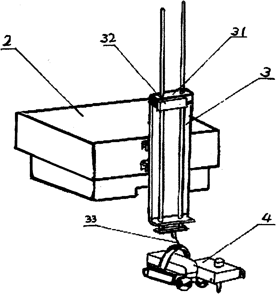
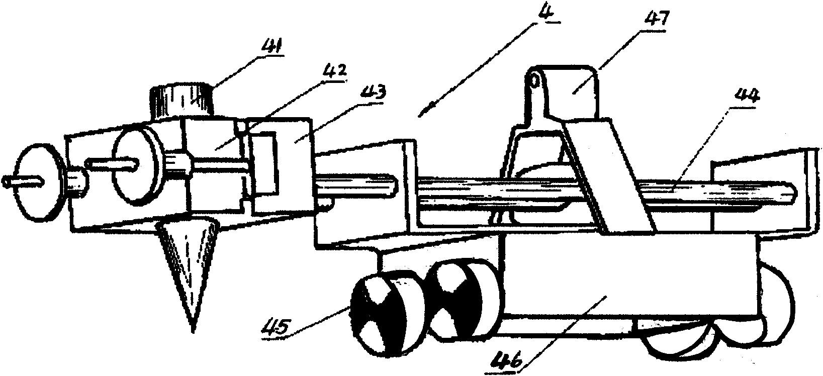
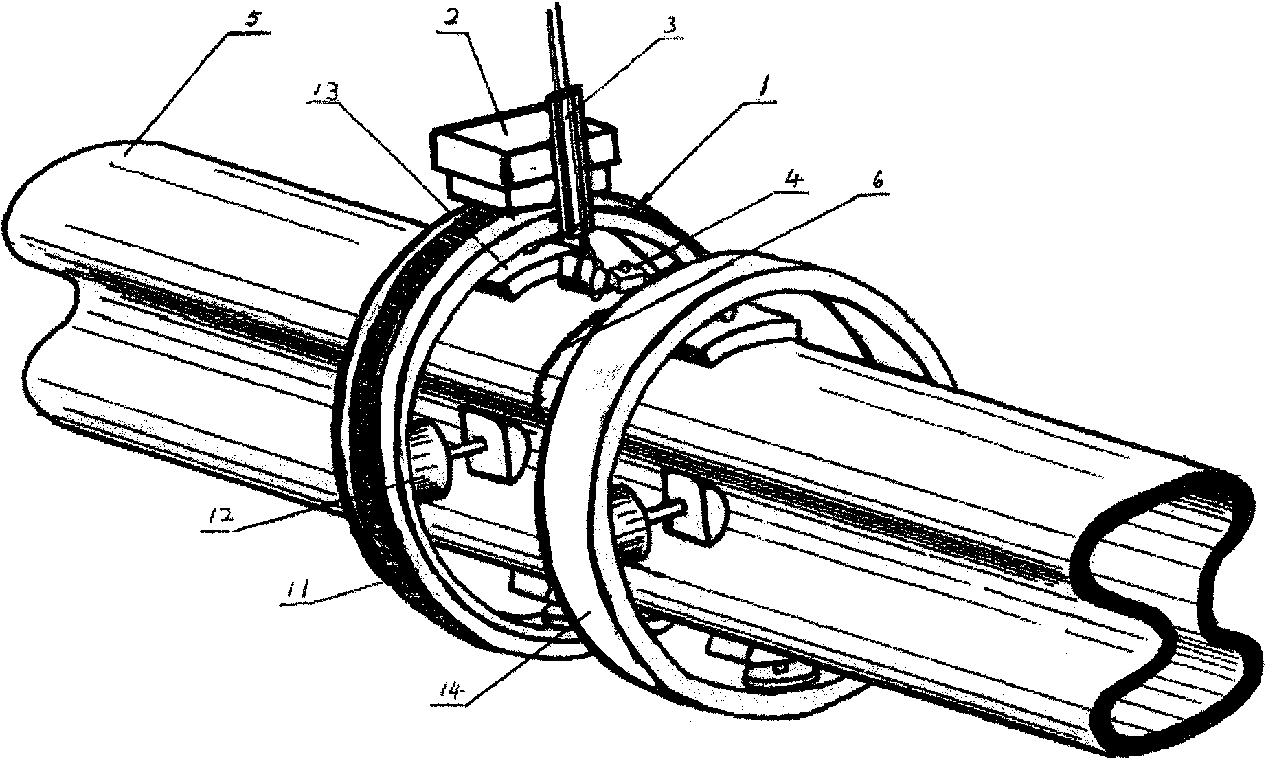
[0017] by figure 1 , figure 2 with image 3 Shown, an automatic welding and cutting device for corrugated pipes with special-shaped cross-sections is mainly composed of clamping ring guide 1, two-way locking welding / cutting trolley 2, height tracking device 3 and bellows contour detecting and tracking device 4. The hydraulic mechanism 12 is installed on the quick disassembly and assembly guide rail 11 for position automatic welding. The concave shaping block 13 and the convex shaping block 14 form the clamping ring guide 1, and the welding / cutting trolley 2 is equipped with a two-way locking mechanism to make it bidirectional The...


PUM


Abstract

The invention discloses an automatic welding and cutting device for a modified cross-section bellows, mainly comprising a clamping annular guide rail (1), a bidirectional locking and welding / cutting trolley (2), a high-low tracing device (3) and a bellows profile detecting and tracing device (4), wherein the welding / cutting trolley (2) is connected with the high-low tracing device (3) which is provided with a high-low tracing module (31) and a high-low sliding block (32); the high-low tracing module (31) is flexibly connected with the bellows profile detecting and tracing device (4); and a clamping mechanism (42), a two-dimensional laser welding joint detection device (43), a swing mechanism (44), a linear velocity absolute coded disc (46) and the like are arranged on the bellows profile detecting and tracing device (4). The invention has the advantages of compact and simple structure, low construction cost and simpleness and easiness in use and maintenance.

Description

Technical field [0001] The invention relates to an automatic welding and cutting device, in particular to an automatic welding and cutting device for corrugated pipes with special-shaped sections. Background technique [0002] In oil field wellhead engineering, special-shaped cross-section bellows needs to be welded, and the welded joint section is 8-shaped. After the special-shaped section corrugated pipe is prefabricated, it needs to be assembled, welded and tested on site. After the welding seam of one section of the pipe is qualified, the pipe that has been taken over is driven into the ground, and then the next section of pipe is spliced ​​until the required design length is reached. [0003] At present, the on-site installation and welding of this special-shaped corrugated pipe mainly has the following problems: the processing of the groove is difficult. Because the test piece is a "8"-shaped corrugated pipe, conventional groove processing equipment cannot be used for groov...

Claims


Application Information

Patent Timeline
IPC IPC(8): B23K37/00G01B21/20
Inventor 陶兴华曾义金马开华牛新明陈天成薛龙邹勇涂玉林刘鹏胡彦峰
Owner CHINA PETROLEUM & CHEM CORP
Learn More