Energy-saving heat pump and co-generation coupled heating system and coupled heating method

A coupling system and combined heat and power technology, applied in the energy field, can solve the problems of heating loads that cannot be expanded and waste heat, etc., and achieve the effects of saving investment, operation and maintenance workload, saving floor space, and improving thermal economy

Inactive Publication Date: 2012-07-18
NORTH CHINA ELECTRIC POWER UNIV (BAODING)
View PDF5 Cites 6 Cited by
  • Summary
  • Abstract
  • Description
  • Claims
  • Application Information

AI Technical Summary

Problems solved by technology

However, due to the influence of the minimum exhaust steam volume of the steam turbine, when the steam extraction volume is at its maximum, a large amount of exhaust steam from the steam turbine still enters the condensing equipment, which wastes a lot of waste heat, and at the same time, the heating load cannot be expanded.

Method used


Image

  • Energy-saving heat pump and co-generation coupled heating system and coupled heating method
  • Energy-saving heat pump and co-generation coupled heating system and coupled heating method
  • Energy-saving heat pump and co-generation coupled heating system and coupled heating method

Examples


Embodiment 1

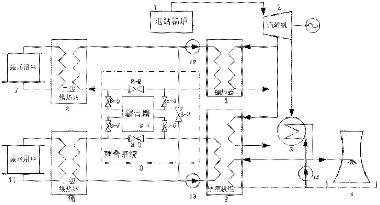
[0019] figure 1 It is a schematic diagram of the structural form of a heat pump and cogeneration coupled heating system. The system adopts the realization form of dual heat network heating, including steam turbines, steam turbine condensing equipment, steam turbine circulating cooling equipment, steam absorption heat pumps, and heat network heaters. , secondary heat exchange station and corresponding pipelines and ancillary equipment.

[0020] Boiler 1 is connected to steam turbine 2 through pipelines, and the exhaust steam of steam turbine 2 is connected to steam turbine condensing equipment 3; the circulating water outlet of steam turbine condensing equipment 3 is connected to circulating water cooling equipment 4 and steam absorption heat pump unit 9 through pipelines, and the circulation cooling The circulating water return water of equipment 4 and heat pump unit 9 is connected to steam turbine condensing equipment 3 via circulating water pump 14; The return water of the ...

Embodiment 2

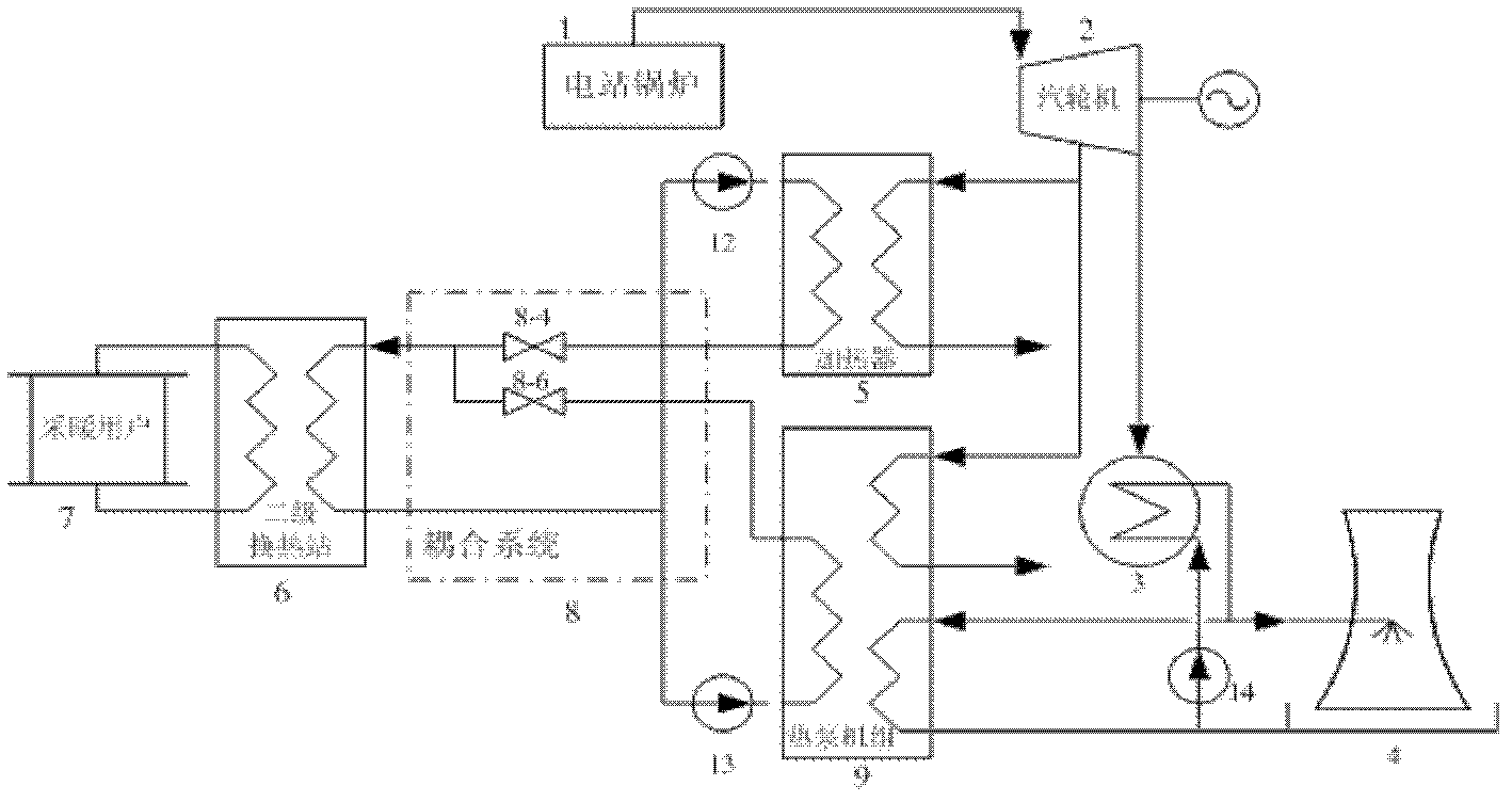
[0024] figure 2 Shown is a schematic diagram of the structural form of the heat pump and cogeneration coupled heating system of the simplified coupled system. The system adopts the realization form of single heating network heating, including steam turbine, steam turbine condensing equipment, steam turbine circulating cooling equipment, steam absorption heat pump, heating network heater, heat exchange station and corresponding pipelines and auxiliary equipment. In the figure, the structure of the coupling system is that the heater-side inlet valve 8-4 connected to the heat network heater 5 and the heat pump-side inlet valve 8-6 connected to the heat pump unit are jointly connected to the coupling system, and are connected to each two through the coupling system. stage heat exchange station, the heat network return water pipe is connected to the inlet end of the first heat network circulating water pump 12 and the second heat network circulating water pump 13; figure 1 same. ...


PUM


Abstract

The invention discloses an energy-saving heat pump and a co-generation coupled heating system and a coupled heating method, belonging to the field of energy sources. The system is composed of a steam turbine, a steam-turbine condensing plant, steam-turbine circulation cooling equipment, a steam-absorption heat pump, a heat network heater, a coupler, a heat-exchange station, corresponding pipelines and accessory equipment. The system utilizes the heat pump and the co-generation heat network heater to heat circulating water of a heat network, the heat pump uses circulating cooling water of a generating plant as a low-temperature heat source, the extracted steam of the steam turbine is utilized as a driving heat source, and the heat of the circulating cooling water is extracted to heat the circulating water of the heat network. The water yield and temperature of water from the heat pump and water from the heat network heater are distributed and adjusted through the coupler, and the heating temperature and the rate of flow in a full heating season are qualified. According to the method, a peak heater is cancelled, so the occupied area and the investment are reduced. The heat pump can have basic heat load, the residual heat is extracted to the maximum extent, the heating capacity is increased, the economical efficiency of the heat pump is maximized, and the purposes of energy saving and emission reduction are achieved.

Description

technical field [0001] The invention belongs to the field of energy, and in particular relates to an energy-saving heat pump and cogeneration coupled heat supply system and a coupled heat supply method. technical background [0002] The heat pump unit can consume a small amount of heat and extract heat from a low-temperature heat source, thereby obtaining more heating heat than the consumed heat, which has considerable economy. Heat pump units, especially steam-driven heat pump units, have many advantages in thermal power plants. 1. The driving steam of the heat pump unit can use the extraction steam of the steam turbine in the thermal power plant, which is convenient to obtain; 2. The condensing equipment of the power plant has a large number of low-temperature Waste heat can be used as a high-quality low-temperature heat source for heat pump units; 3. Thermal power plants have a large amount of heat load, which can meet the basic load requirements of heat pump units. The ...

Claims


Application Information

Patent Timeline
Patent Type & Authority Applications(China)
IPC IPC(8): F24D3/18F24D3/10F24D19/00
Inventor 于刚张永生靳涛张光卞双鞠翠玲邢长燕
Owner NORTH CHINA ELECTRIC POWER UNIV (BAODING)
Why Eureka
Try Eureka