
Brushless multi-working-condition direct-current electrically-driven pump

A DC motor, electric pump technology, applied in pump control, non-variable capacity pump, engine components, etc., can solve the problem that the operating point is not adjustable or the adjustable range is small, the working state of the oil pump is single, and the power-to-weight ratio is low. problems, to achieve the effect of good manufacturing process and maintenance, suitable for industrial development, and high power-to-weight ratio

Inactive Publication Date: 2015-04-08
JINCHENG NANJING ELECTROMECHANICAL HYDRAULIC PRESSURE ENG RES CENT AVIATION IND OF CHINA
View PDF8 Cites 6 Cited by
  • Summary
  • Abstract
  • Description
  • Claims
  • Application Information

AI Technical Summary

Problems solved by technology

[0002] For many years, the development of transport aircraft and its fuel pumps has been slow due to the long model replacement period and other reasons. The fuel pumps have a single working state, low power-to-weight ratio, low efficiency, and difficult maintenance. The main reason is that these pumps are driven by brushed motors. , the speed is low, no control, the operating point is not adjustable or the adjustable range is very small

Method used


Image

  • Brushless multi-working-condition direct-current electrically-driven pump
  • Brushless multi-working-condition direct-current electrically-driven pump
  • Brushless multi-working-condition direct-current electrically-driven pump

Examples


Embodiment Construction

[0018] See the specific implementation Figure 1 to Figure 6 . The present invention will be further described in detail through specific embodiments below.

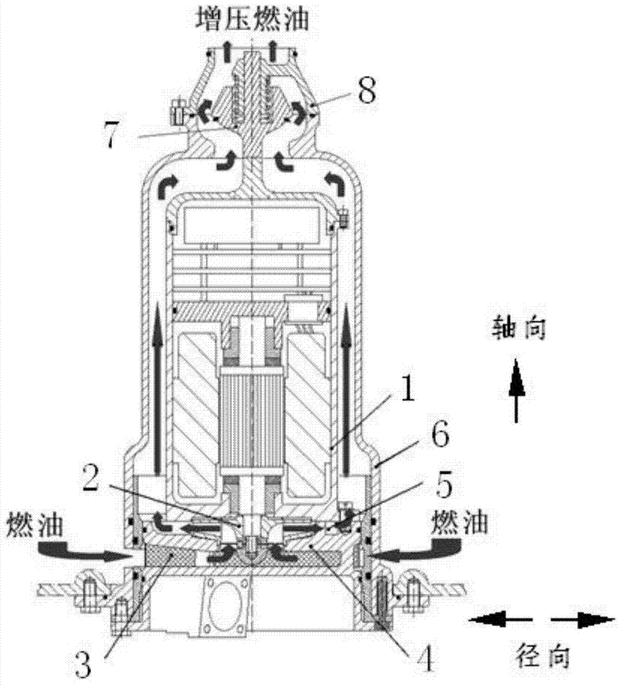
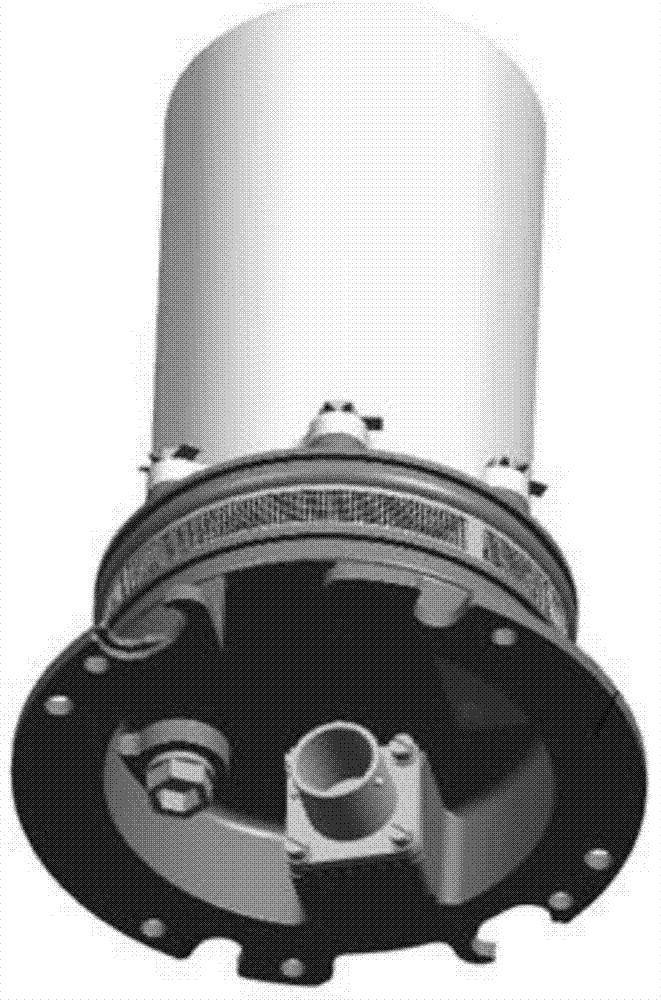
[0019] The multi-working condition brushless DC electric pump is composed of two parts: a pump core assembly and a disassembled self-sealing assembly, wherein the pump core assembly includes a brushless DC motor 1, a centrifugal impeller 2, a filter screen 3, a pump inlet section 4 and a diameter The guide vane 5 is equipped with a self-sealing assembly including a pump cover 6 , a one-way valve 7 and a valve housing 8 . Such as image 3 , Figure 4 shown. The centrifugal impeller (2) installed on the shaft of the brushless DC motor (1) is driven by a brushless DC motor (1) to rotate, and the fuel in the suction tank passes through the filter screen (3) and the radial channel of the fan-shaped section. Enter the pump inlet section (4), flow through the centrifugal impeller (2) for centrifugal boosting, and then ente...


PUM


Abstract

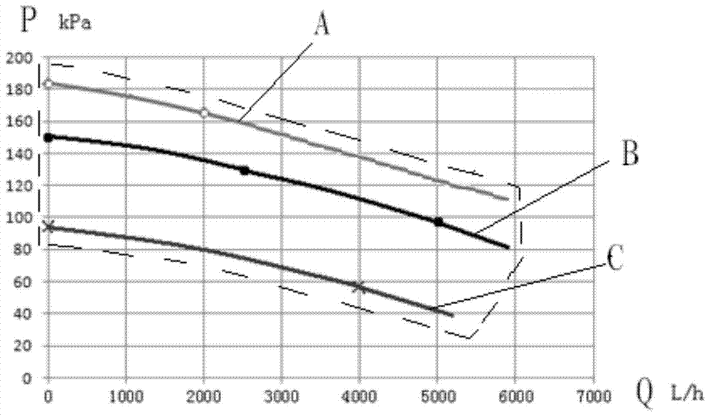
The invention belongs to the technical field of aircraft fuel systems, and relates to a design and a structure of a brushless multi-working-condition direct-current electrically-driven pump. The brushless multi-working-condition direct-current electrically-driven pump is characterized in that a brushless direct-current motor with multi-state working capability drives an impeller which is arranged on a shaft of the brushless direct-current motor to rotate; pumping fuel oil flows through a filter screen, a pump core shell and the impeller to be subjected to centrifugal supercharging, then flows into a radial guide vane for further diffusion supercharging and flows in an axial direction; the supercharged fuel oil passes through an annular flow channel positioned between a pump cover and the shell of the motor to converge and is output through a check valve at the top of the pump cover and a valve shell. The former fuel delivery pump is designed according to the maximum working condition even if being in multiple working states and has no self-adjusting capability, the flow pressure is controlled by virtue of an adjusting valve and the working is carried out on a single curve; however, due to the multiple working conditions which are designed for being matched with the brushless multi-working-condition direct-current electrically-driven pump, the requirement on the current working condition can be rightly met when the pump is in various states, and the pump works on a group of similar flow and pressure curve so as to form a larger working enveloping range.

Description

technical field [0001] A multi-working-condition brushless DC electric pump belongs to the technical field of aircraft fuel systems, and relates to the design and structure of a wide-envelope centrifugal fuel pump driven by a brushless DC motor and capable of working at multiple working conditions. Background technique [0002] For many years, the development of transport aircraft and its fuel pumps has been slow due to the long model replacement cycle and other reasons. The fuel pumps have a single working state, low power-to-weight ratio, low efficiency, and difficult maintenance. The main reason is that these pumps are driven by brushed motors. , low speed, no control, the operating point can not be adjusted or the adjustable range is extremely small. [0003] In recent years, civil aviation aircraft, transport aircraft and seaplanes have continuously improved the requirements of high reliability, long life, easy maintenance, high power-to-weight ratio and adaptive perfor...

Claims


Application Information

Patent Timeline
Patent Type & Authority Applications(China)
IPC IPC(8): F02M37/08F04D15/00
Inventor 刘晓东周利华张进王文平李述林易晓红
Owner JINCHENG NANJING ELECTROMECHANICAL HYDRAULIC PRESSURE ENG RES CENT AVIATION IND OF CHINA
Learn More