Method for forming annular end tooth edge line of arc-shaped end tooth vertical mill

A technology of circular arc end teeth and end mills, which is applied in the field of circular arc edge line modeling, and can solve problems such as easy interference and difficulty in ensuring smooth transition

Inactive Publication Date: 2011-11-23
SOUTHWEST JIAOTONG UNIV +1
View PDF4 Cites 11 Cited by
  • Summary
  • Abstract
  • Description
  • Claims
  • Application Information

AI Technical Summary

Problems solved by technology

In the grinding and manufacturing of traditional annular end mills, because there is no guidance from the theoretical annular edge line model, the rake face of the annular end tooth is often formed by direct grinding wheel feedi

Method used


Image

  • Method for forming annular end tooth edge line of arc-shaped end tooth vertical mill
  • Method for forming annular end tooth edge line of arc-shaped end tooth vertical mill
  • Method for forming annular end tooth edge line of arc-shaped end tooth vertical mill

Examples


Embodiment

[0092] An end mill with a ring radius of 3 is selected as a design example. The detailed parameters are as follows:

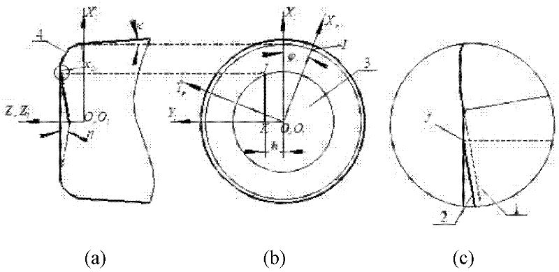
[0093] Peripheral edge is equal helix angle edge line, helix angle β=39°, circumferential tooth taper angle κ=4°; end tooth inclination angle η=3°, tooth eccentricity h=1, tooth over-center amount l=2.

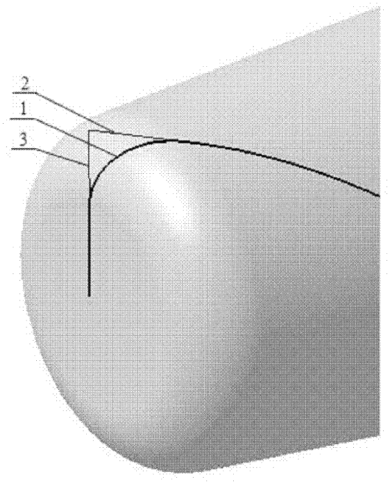
[0094] The formed end tooth straight edge and annular edge are as attached Figure 4 Shown. As attached Figure 4 As shown in a, the straight edge of the end tooth has an inclination angle, Figure 4 b represents the off-center amount and over-center amount of the straight edge, Figure 4 The annular edge of the end tooth shown in c is smoothly connected with the straight edge of the end tooth and the edge line of the peripheral tooth.


PUM


Abstract

The invention discloses a method for forming an annular end tooth edge line of an arc-shaped end tooth vertical mill. In the method, a tool making unit processes and forms the arc-shaped end tooth vertical mill according to a mathematical model built by a data control unit and parameter data output by the data control unit. The data control unit builds the mathematical model and output the parameter data by the following steps: inputting the diameter and helical angle of the tool; building the mathematical model of the end tooth edge line; building a mathematical model of the annular end tooth edge line by resolving equation of tangent at the end of a peripheral tooth edge line, resolving the intersection point of the extended line of a straight edge and the tangent at the end of the peripheral tooth edge line, determining the plane defined by the straight edge and the tangent at the end of the peripheral tooth edge line, and resolving the intersection line of the plane and an annularsurface to form an annular edge line; and finally outputting the parameter data of the annular edge line to the tool manufacturing unit. The invention establishes a method for forming the end tooth straight edge line and annular edge line of a vertical mill, which is used for building the mathematical model of the annular vertical mill and instructing manufacturing and processing in order to ensure the smooth connection of the peripheral tooth edge line and the end tooth straight edge.

Description

Technical field [0001] The invention relates to the field of cutting tool manufacturing, in particular to a method for modeling the arc edge line of an arc end milling cutter for CNC machine tool processing. Background technique [0002] The arc end mill is a commonly used new structural tool for CNC machine tools to process curved surfaces. It is widely used in mold manufacturing, automobile manufacturing, aerospace, electronic communication product manufacturing and other industries. In the design and manufacture of arc-end end mills, the design and sharpening of the cutting edge curve is very important, because the cutting edge not only determines the shape of the tool, thereby determining the shape of the machined surface (during forming), but also the cutting tool Performance and processing quality play an important role. In the grinding and manufacturing of traditional ring end tooth end mills, because there is no guide of the theoretical ring edge line model, the ring end...

Claims


Application Information

Patent Timeline
IPC IPC(8): B23P15/34
Inventor 黎荣丁国富程雪峰米蓉邹益胜江磊马术文
Owner SOUTHWEST JIAOTONG UNIV
Why Eureka
Try Eureka