Supercharge Your Innovation With Domain-Expert AI Agents!

Long-rail Z-shaped feeding mechanism

A technology of feeding mechanism and long rail, which is applied in the field of long rail Z-shaped feeding mechanism for key machines, and can solve problems such as low production efficiency, affecting the normal processing of key machines, and jamming of the pushing mechanism.

Active Publication Date: 2013-02-06
YIFENG MFG
View PDF5 Cites 0 Cited by
  • Summary
  • Abstract
  • Description
  • Claims
  • Application Information

AI Technical Summary

Problems solved by technology

[0002] The key machine is a fully automatic processing equipment that can automatically grind the teeth of the key body in batches. However, during the actual grinding process of the key body, it was found that the gear grinding device can only grind one key body at a time, while the conventional When the pushing mechanism is used for feeding, because the conventional pushing mechanism has no space-occupying function, the key blank can only be continuously fed to the gear grinding device, and the gear grinding device needs to be used when grinding the previous key body. The pusher mechanism suspends feeding, but the conventional pusher mechanism does not have a pause feeding device, and can only rely on adjacent key bodies to resist each other to realize pause feeding, but because the key machine vibrates when the key machine is working, the key bodies that resist each other are vibrating Under the action, stacking is easy to occur and the pushing mechanism is prone to jamming, which seriously affects the normal processing of the key machine, increases maintenance costs, and lowers production efficiency

Method used


Image

  • Long-rail Z-shaped feeding mechanism
  • Long-rail Z-shaped feeding mechanism
  • Long-rail Z-shaped feeding mechanism

Examples


Embodiment Construction

[0024] In order to facilitate the understanding of those skilled in the art, the present invention will be further described below in conjunction with the embodiments and accompanying drawings, and the contents mentioned in the embodiments are not intended to limit the present invention.

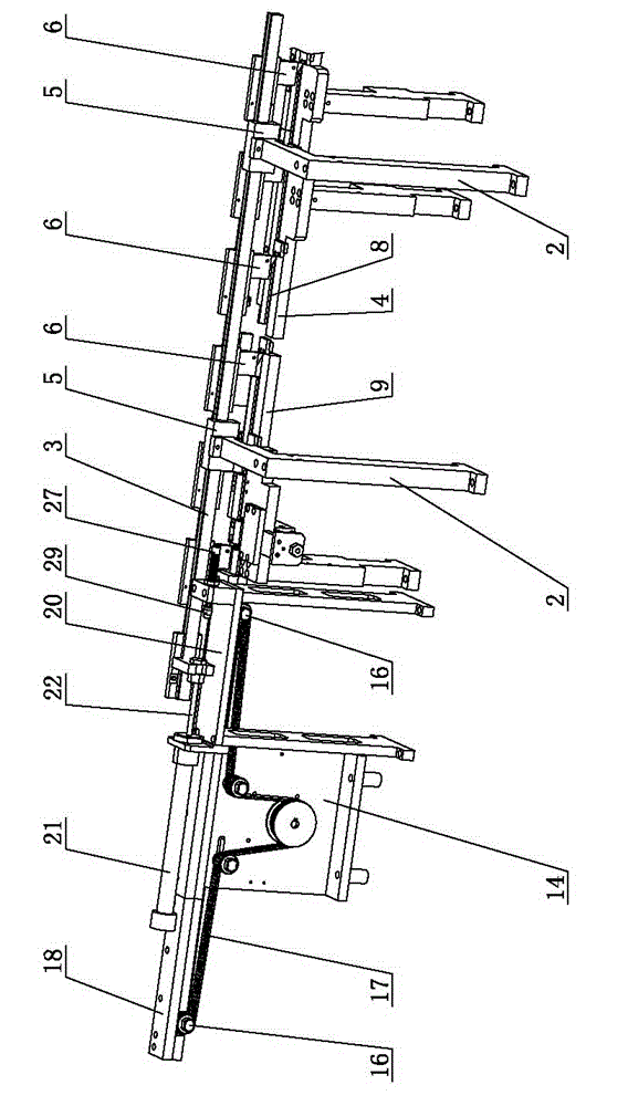
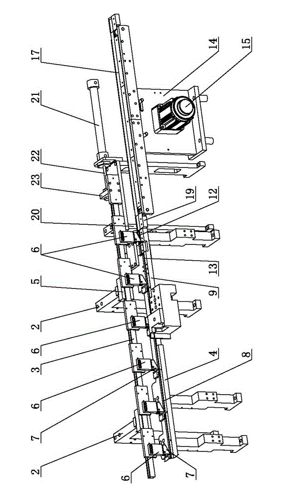
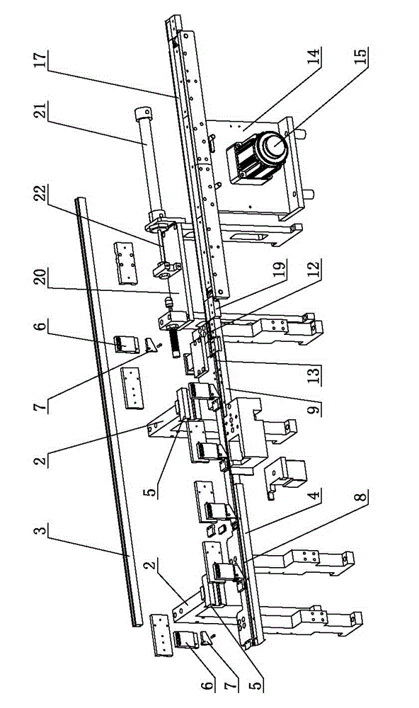
[0025] Such as Figures 1 to 8 As shown, a long rail Z-shaped feeding mechanism includes a frame 1, a primary feeding device arranged on the frame 1 according to the working order, a placeholder device and a secondary feeding device, and the secondary feeding device includes Push rod support 2, feed push rod 3, feed base 4 and the feed driving device for driving the feed push rod 3 to move left and right, the push rod support 2 is arranged on the frame 1, and the push rod support 2 is equipped with a slide The rail seat 5, the feed push rod 3 is movably installed on the slide rail seat 5, the feed push rod 3 is fixedly equipped with at least two shifting blocks 6, and each shifting block 6 i...


PUM


Abstract

The invention relates to the technical field of key processing equipment, and in particular relates to a long-rail Z-shaped feeding mechanism used for a key cutting machine. The long-rail Z-shaped feeding mechanism comprises a frame, and a first-level feeding device, an occupying device and a second-level feeding device which are arranged on the frame according to a working sequence, wherein the second-level feeding device comprises a push rod bracket, a feeding push rod, a feeding base and a feeding driving device used for driving the feeding push rod to move left and right; the push rod bracket is arranged on the frame; a slide rail base is arranged on the push rod bracket; the feeding push rod is moveably arranged on the slide rail base; at least two stirring blocks are fixedly arranged on the feeding push rod; each of the stirring blocks is hinged with a hinging push block; and a conveying slide rail is arranged on the feeding base. The design of an occupying slide slot is adoptedin the long-rail Z-shaped feeding mechanism, thereby ensuring that only one key blank enters into a tooth grinding process each time, preventing equipment from being blocked by a plurality of key blanks simultaneously entering into a tooth grinding device, ensuring the normal operations in all the processing processes of the key cutting machine, and greatly promoting the production efficiency of the key cutting machine.

Description

technical field [0001] The invention relates to the technical field of key processing equipment, in particular to a long rail Z-shaped feeding mechanism for key machines. Background technique [0002] The key machine is a fully automatic processing equipment that can automatically grind the teeth of the key body in batches. However, during the actual grinding process of the key body, it was found that the gear grinding device can only grind one key body at a time, while the conventional When the pushing mechanism is used for feeding, because the conventional pushing mechanism has no space-occupying function, the key blank can only be continuously fed to the gear grinding device, and the gear grinding device needs to be used when grinding the previous key body. The pusher mechanism suspends feeding, but the conventional pusher mechanism does not have a pause feeding device, and can only rely on adjacent key bodies to resist each other to realize pause feeding, but because the...

Claims


Application Information

Patent Timeline
Patent Type & Authority Patents(China)
IPC IPC(8): B24B19/00
Inventor 赖秀兴
Owner YIFENG MFG
Features
  • R&D
  • Intellectual Property
  • Life Sciences
  • Materials
  • Tech Scout
  • Unparalleled Data Quality
  • Higher Quality Content
  • 60% Fewer Hallucinations
Learn More