Mould structure of horizontal rotary bottle blowing machine

A blow molding machine and mold technology, which is applied in the field of blow molding machines, can solve the problems that the horizontal rotary blow molding machine cannot arrange cooling water channels, etc., and achieve the effect of improving the cooling effect, increasing the contact area, and simplifying the design

Inactive Publication Date: 2011-11-23
天良智能设备(上海)股份有限公司
View PDF5 Cites 2 Cited by
  • Summary
  • Abstract
  • Description
  • Claims
  • Application Information

AI Technical Summary

Problems solved by technology

In the prior art, the mold structure of the blow molding machine can only be used in the vertical blow molding machine, the main reason is that the cooling water circuit cannot be arranged in the horizontal rotary blow molding machine due to the separation of the left half mold and the right half mold

Method used


Image

  • Mould structure of horizontal rotary bottle blowing machine
  • Mould structure of horizontal rotary bottle blowing machine
  • Mould structure of horizontal rotary bottle blowing machine

Examples


Embodiment Construction

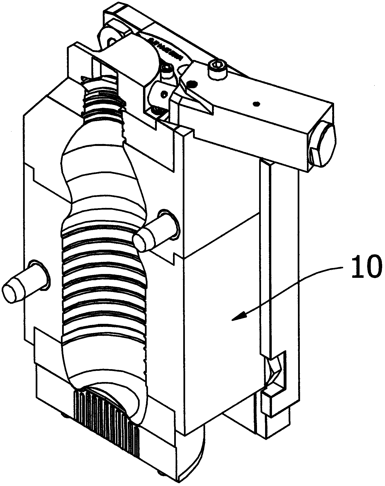
[0018] Such as figure 1 , Figure 4 As shown, a specific embodiment of the mold structure of the horizontal rotary blow molding machine of the present invention, the mold structure includes a left half mold 10 and a right half mold 20 .

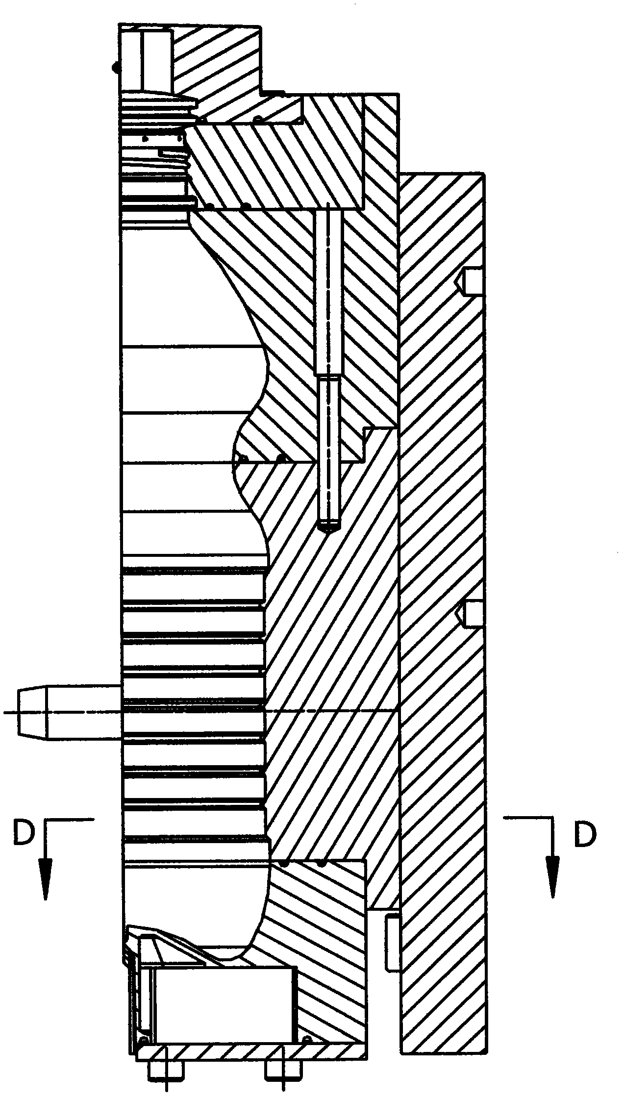
[0019] Such as figure 2 , Figure 5 As shown, each of the left half-mold 10 and the right half-mold 20 at least includes a bottle cavity and a cooling water circuit arranged around the bottle cavity. Left half mold 10 is made up of left upper half mold and left lower half mold, and right half mold 20 is made up of right upper half mold and right lower half mold.

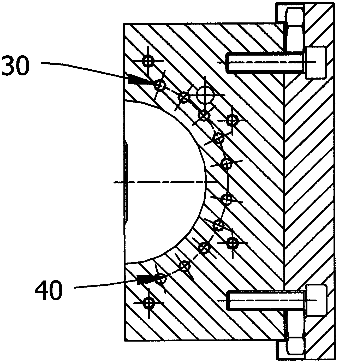
[0020] Such as image 3 As shown, the cooling water circuit includes a water inlet 30 and a water outlet 40; as Image 6 As shown, the cooling water circuit includes a water inlet 50 and a water outlet 60 . The cooling water circuit is close to the cavity wall of the bottle cavity. The cooling waterway is a continuous waterway. The cooling water path is bent and arranged ar...


PUM


Abstract

The invention discloses a mould structure of a horizontal rotary bottle blowing machine. The mould structure comprises a left half model and a right half model; and the left half model and the right half model at least respectively comprise a bottle cavity and a cooling water path arranged around the bottle cavity. In the mould structure of the horizontal rotary bottle blowing machine disclosed by the invention, the cooling water path of the left half model is separated from the cooling water path of the right half model, so that the horizontal rotary bottle blowing machine is possible to be used. The bending structure of the cooling water path ensures that the contact area of the cooling water path and the bottle cavity is greatly increased, and the cooling effect is greatly improved. The cooling water path is one continuous water path, so the designs of a water inlet pipe and a water outlet pipe are greatly simplified. By virtue of the design of the cooling water path, products are cooled fast in a mold cavity, so that the horizontal rotary bottle blowing machine can blow out acceptable product bottles to meet the production capacity requirements of equipment.

Description

technical field [0001] The invention relates to the technical field of bottle blowing machines, in particular to a mold structure of a horizontal rotary bottle blowing machine. Background technique [0002] The bottle blowing machine is a heating and feeding device that blows softened plastic particles into a bottle through a certain process. In the prior art, the mold structure of the blow molding machine can only be used in the vertical blow molding machine, the main reason being that the cooling water circuit cannot be arranged in the horizontal rotary blow molding machine due to the separation of the left half mold and the right half mold. [0003] Therefore, those skilled in the art are devoting themselves to developing a mold structure for a horizontal rotary bottle blowing machine to overcome the above defects. Contents of the invention [0004] In view of the above-mentioned defects of the prior art, the technical problem to be solved by the present invention is t...

Claims


Application Information

Patent Timeline
Patent Type & Authority Applications(China)
IPC IPC(8): B29C49/48
Inventor 章方雨张家放
Owner 天良智能设备(上海)股份有限公司
Why Eureka
Try Eureka