Eureka AIR delivers breakthrough ideas for toughest innovation challenges, trusted by R&D personnel around the world.

Branch control phase inversion heat exchange system and method based on vapor-liquid heat exchanger

A technology of phase conversion heat and heat exchanger, which is applied in the field of enhanced heat transfer, and can solve the problems of temperature safety margin reduction, corrosion, increase, etc.

Active Publication Date: 2011-11-23
SHANXI SANHESHENG IND TECH
View PDF5 Cites 20 Cited by
  • Summary
  • Abstract
  • Description
  • Claims
  • Application Information

AI Technical Summary

Problems solved by technology

Since the steam will form a liquid film on the wall during the condensation process of the cold source heat exchanger, the supercooling of the condensate cannot be avoided
In addition, due to the heat exchanger area, heat transfer coefficient and heat transfer temperature difference under the design working conditions, it is difficult to adapt to the actual phase change heat under changing working conditions and in different seasons, coupled with the influence of factors such as liquid level fluctuations, so the phase change The thermal process is always accompanied by supercooling of condensate and superheating of steam; the existence of supercooled liquid and superheated steam will reduce the heat transfer capacity of the phase change heat exchanger, and at the same time, due to the existence of natural circulation, the supercooled liquid enters the heat source for heat exchange The device will also reduce the temperature safety margin of the lower wall surface of the evaporating heat exchange surface, and increase the probability of local low-temperature corrosion

Method used


Image

  • Branch control phase inversion heat exchange system and method based on vapor-liquid heat exchanger
  • Branch control phase inversion heat exchange system and method based on vapor-liquid heat exchanger

Examples


Embodiment Construction

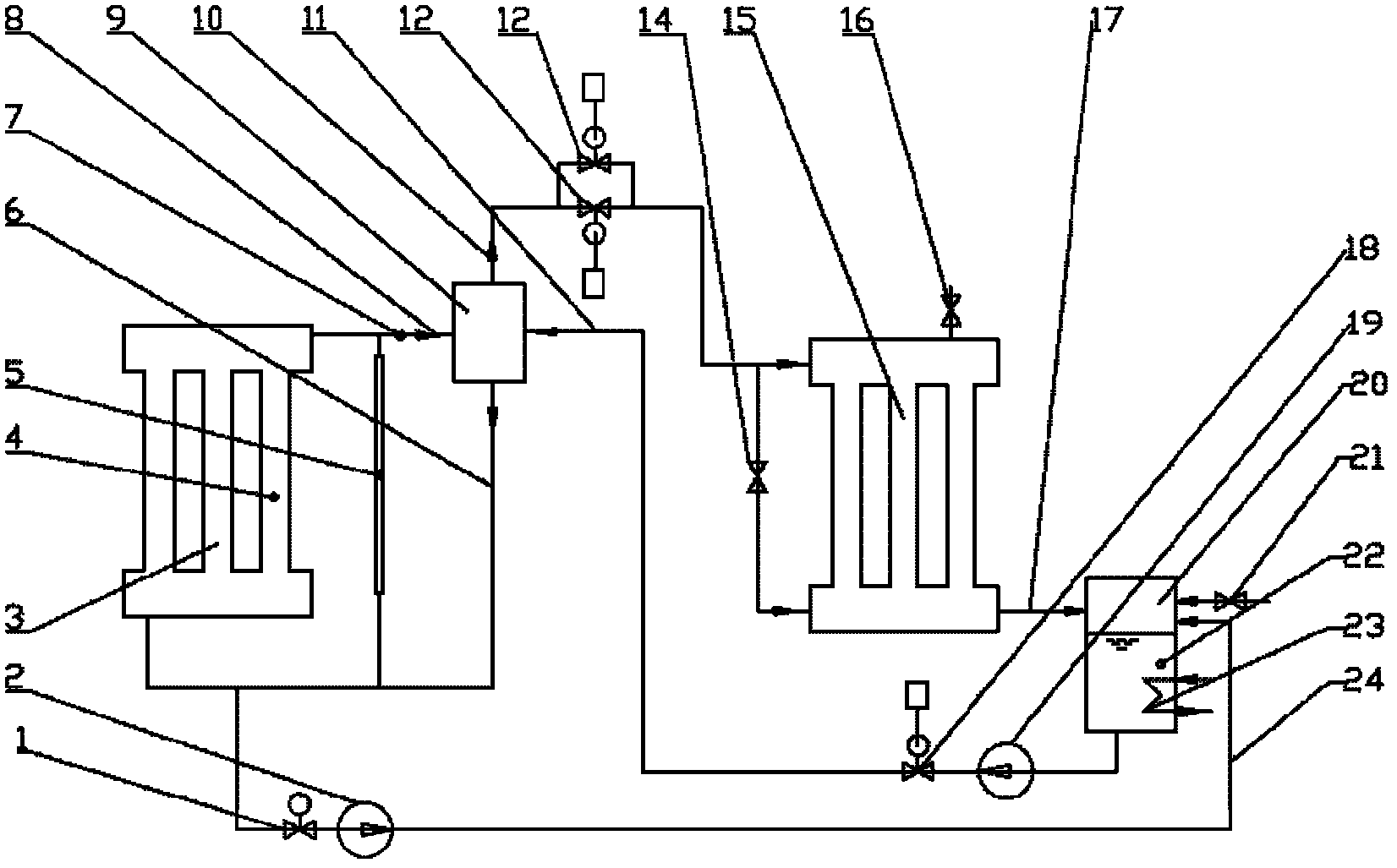
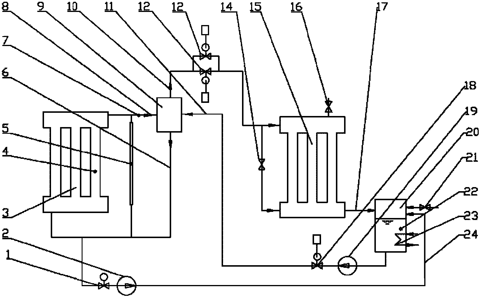
[0083] The split-controlled phase-change heat system and heat exchange method based on the vapor-liquid heat exchanger of the present invention will be further described below in conjunction with the accompanying drawings.

[0084] Such as figure 1 as shown,

[0085] The heat source heat exchanger 3 absorbs the heat of the exothermic fluid flue gas from the heat source (the heat source fluid can also be the tail gas of the production process, etc.) ) is evaporated into steam, and the steam enters the vapor-liquid heat exchanger 9 from the upper header of the heat source heat exchanger 3 through the heat exchanger inlet steam pipe 8 for heat exchange.

[0086] The vapor-liquid heat exchanger 9 can be a hybrid heat exchanger or a surface heat exchanger. The steam after heat exchange from the vapor-liquid heat exchanger 9 reduces the degree of superheat, and flows through the outlet steam pipe 10 of the heat exchanger and is connected in parallel. After the connected A airflow ...


PUM


Abstract

The invention relates to a branch control phase inversion heat exchange system and a branch control phase inversion heat exchange method based on a vapor-liquid heat exchanger. The system comprises a liquid storage tank (20), a heat source heat exchanger (3), a cold source heat exchanger (15) and a vapor-liquid heat exchanger (9); an upper collection tank of the heat source heat exchanger (3) is communicated with the vapor-liquid heat exchanger (9) through a heat exchanger inlet steam pipe (8); a vapor-liquid heat exchanger outlet steam pipe (10) which is arranged on the vapor-liquid heat exchanger (9) is divided into two branches which are communicated with an upper collection tank and a lower collection tank of the cold source heat exchanger (15); the lower collection tank of the cold source heat exchanger (15) is communicated with the upper part of the liquid storage tank (20) through a cold source heat exchanger liquid outlet pipe (17); the bottom of the liquid storage tank (20) is communicated with the vapor-liquid heat exchanger (9) through a heat exchanger inlet condensation liquid pipe (11); and the vapor-liquid heat exchanger (9) is communicated with a lower collection tank of the heat source heat exchanger (3) through a heat exchanger outlet condensation liquid pipe (6). The branch control phase inversion heat exchange system can solve the phenomena of overcooling and overheating and improve heat exchanging efficiency.

Description

technical field [0001] The invention relates to the technical field of safe and controllable enhanced heat transfer, in particular, the invention relates to a separate-controlled phase-change heat system and a heat exchange method based on a vapor-liquid heat exchanger. Background technique [0002] In domestic and foreign enhanced heat transfer technologies and technologies dedicated to waste heat recovery and utilization, many high-efficiency phase-change heat transfer technologies have been developed by utilizing the characteristics of high heat transfer coefficient and uniform temperature of vapor condensation and liquid boiling evaporation. In terms of reducing boiler exhaust gas temperature, recovering waste heat and improving thermal efficiency, heat pipes or other phase conversion heat technologies are often used to control the corrosion and ash deposition speed of the heating surface on the flue gas side through different technical solutions, and better results have ...

Claims


Application Information

Patent Timeline
IPC IPC(8): F28D15/02F28D15/06
Inventor 郝江平闫润生梁世强何京东
Owner SHANXI SANHESHENG IND TECH
Why Eureka
Eureka Blog
Learn More