Electromagnetic encoder

An encoder and electromagnetic technology, which is applied in the field of electromagnetic encoders, can solve the problems of enlarged encoder width and smaller length, and achieve the effect of increasing the received signal strength and reducing the total area

Active Publication Date: 2011-11-23
MITUTOYO CORP
View PDF6 Cites 12 Cited by
  • Summary
  • Abstract
  • Description
  • Claims
  • Application Information

AI Technical Summary

Problems solved by technology

[0009] However, since multiple rows of scale coils are required in the direction of the dial width, the width of the dial, that is, the width of the encoder becomes larger and the length becomes smaller

Method used


Image

  • Electromagnetic encoder
  • Electromagnetic encoder
  • Electromagnetic encoder

Examples


no. 1 approach

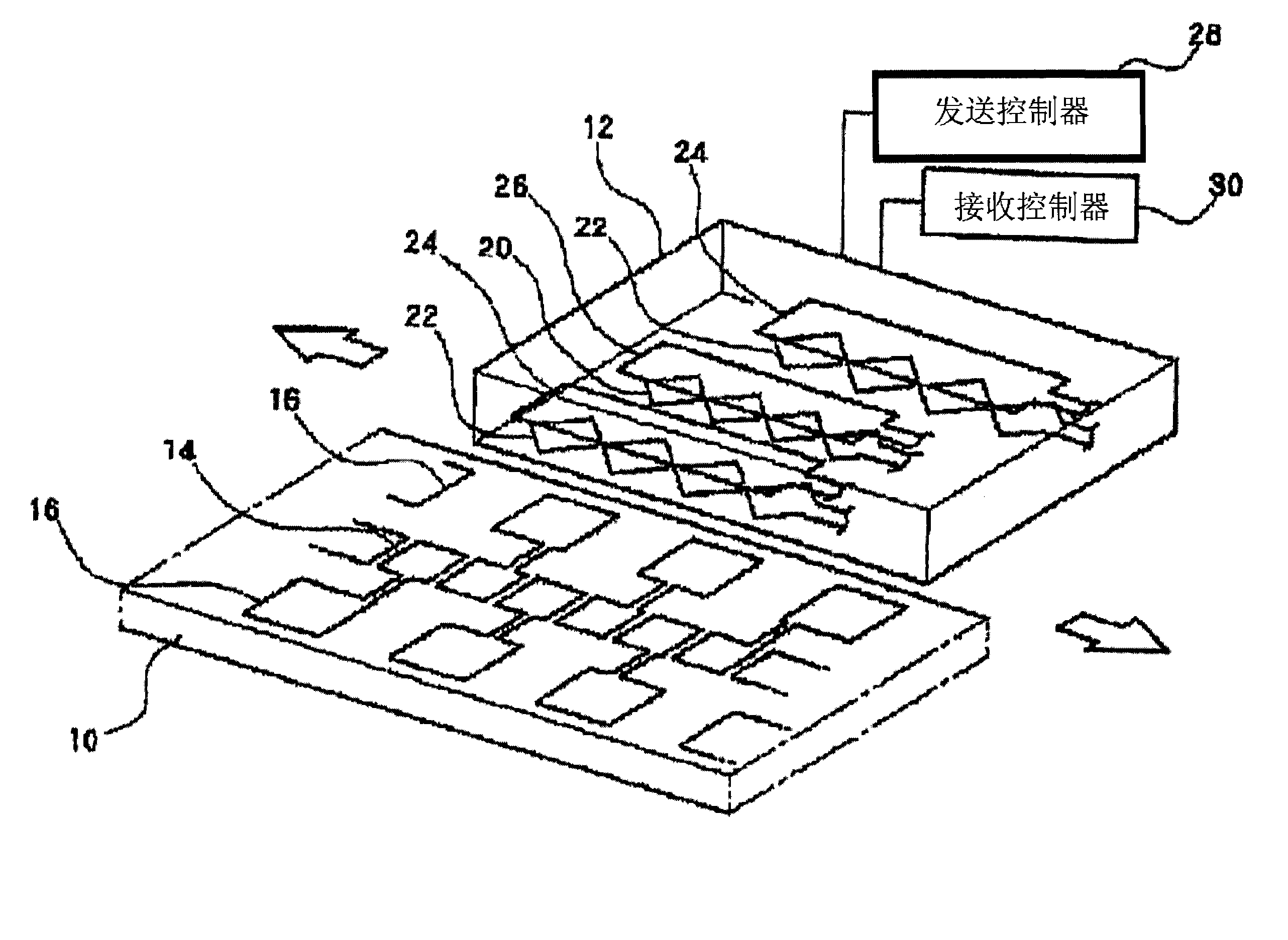
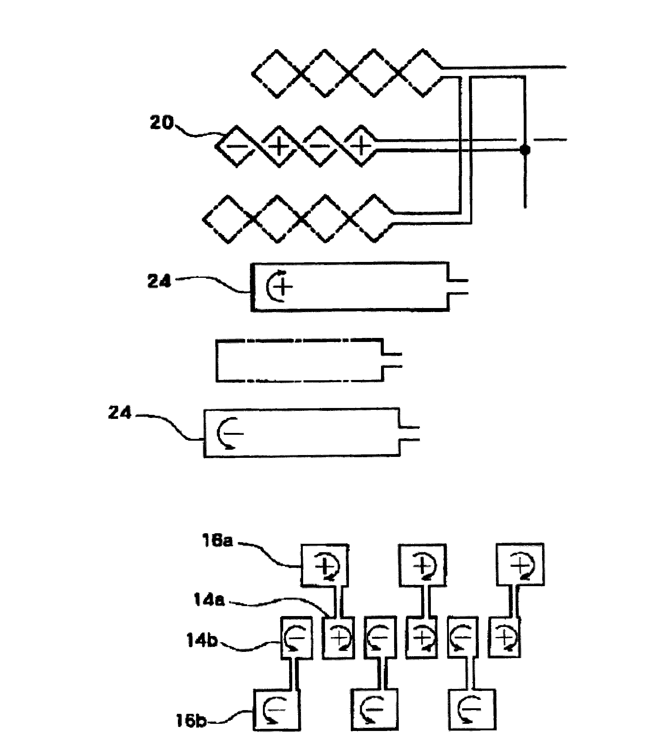
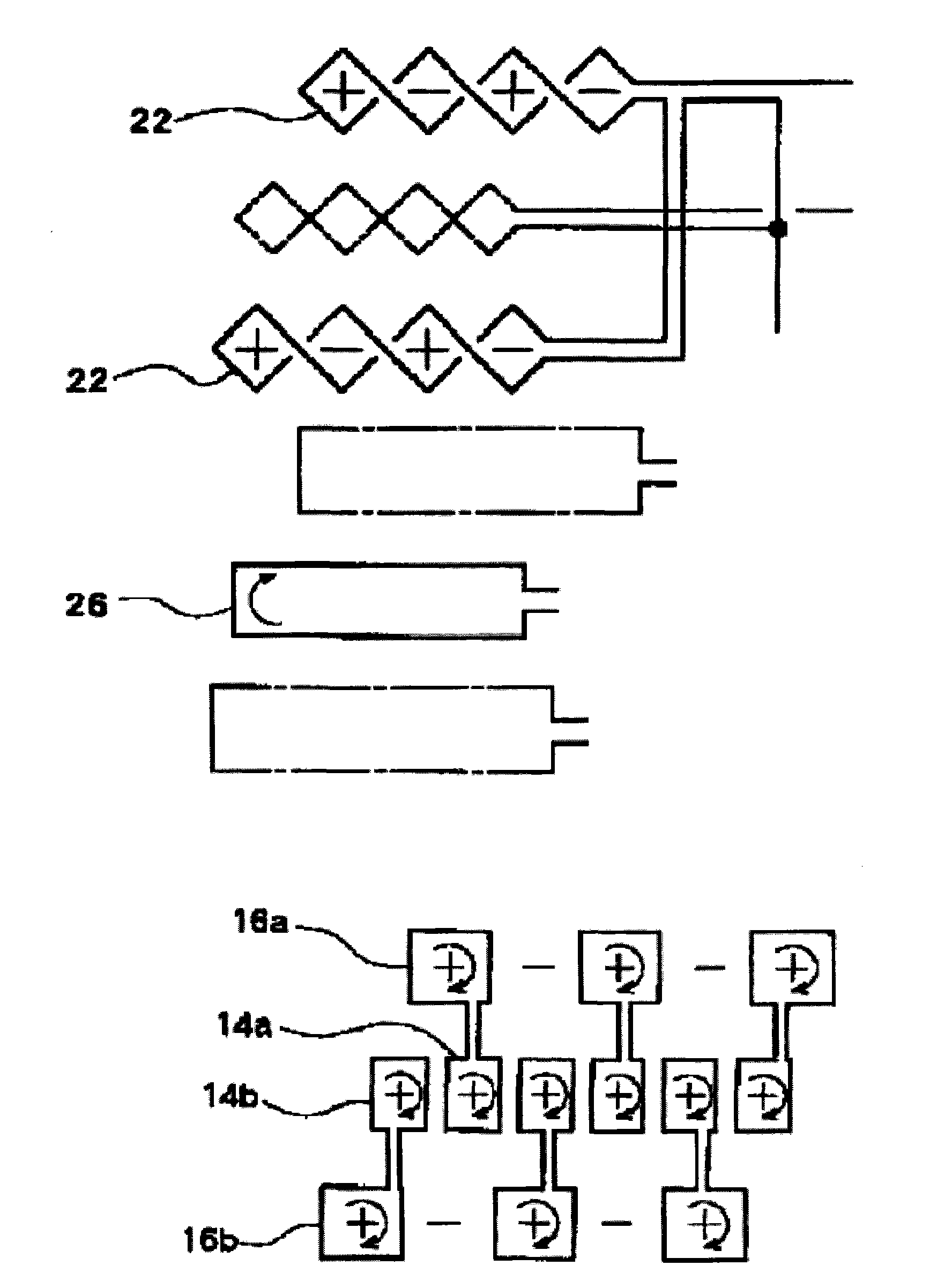
[0024] like Figure 4 As shown, the first embodiment of the non-limiting features of the present invention comprises: a plurality of scale coils 14 arranged on the scale 10 along the measuring direction; and a grid arranged movable relative to the scale 10 in the measuring direction Transmitting coil 24 and receiving coil on 12, wherein the amount of relative movement between scale 10 and grid 12 is detected based on a change in magnetic flux detected by the receiving coil via scale coil 14 when transmitting coil 24 is energized. In the electromagnetic encoder, two sets of receiving coils (20A, 20B) are arranged along the measurement direction, and one of the two sets of receiving coils (for example, 20A) is staggered by 1 relative to the other of the two sets of receiving coils (for example, 20B). Phase of / 2 scale pitch λ.

[0025] The two sets of receiving coils 20A and 20B have the same shape, and are connected to output the difference between the signals of the receiving...


PUM


Abstract

The present invention provides an electromagnetic encoder includes a number of scale coils arranged on a scale disc along a measuring direction; and transmitting coils and a plurality of receiving coils arranged on a grid to be movable relative to the scale disc in the measuring direction, in which a relative movement amount between the scale disc and the grid is detected based on variation in magnetic flux detected by the receiving coils via the scale coils at the time of exciting the transmitting coils, and the receiving coils are provided in the measuring direction to be a plurality of sets, one of the sets of the receiving coils being displaced by a 1 / 2 phase of a scale pitch relative to the other set of the receiving coils.

Description

technical field [0001] The invention relates to an electromagnetic encoder. In particular, the present invention relates to a high-precision and low-cost electromagnetic encoder suitable for calipers, indicators, linear scales, micrometers, etc., by using a small dial The scale width, that is, the encoder width, is used to reduce the offset to achieve a large signal strength, and the electromagnetic encoder has a strong change in the pitching direction. Background technique [0002] As disclosed in Patent Document 1 and Patent Document 2, and as figure 1 In the example shown in Patent Document 2, a known electromagnetic encoder has: a plurality of scale coils (scale coils) 14, 16 arranged on a scale (scale) 10 along the measurement direction; ) (also referred to as a slider) 12 with transmitting coils 24, 26 and receiving coils 20, 22, the grid 12 can move relative to the scale 10 in the measuring direction. In the electromagnetic encoder, the amount of relative movement ...

Claims


Application Information

Patent Timeline
Patent Type & Authority Applications(China)
IPC IPC(8): G01D5/20
CPCG01D5/2086
Inventor 佐佐木康二
Owner MITUTOYO CORP
Why Eureka
Try Eureka