Linear filter-based harmonic current detection method in three-phase four-wire system
A technology of three-phase four-wire system and detection method, which is applied in the field of electric power system, can solve problems such as poor real-time performance, large amount of calculation, and difficult selection of wavelet base
- Summary
- Abstract
- Description
- Claims
- Application Information
AI Technical Summary
Problems solved by technology
Method used
Image
Examples
Embodiment 1
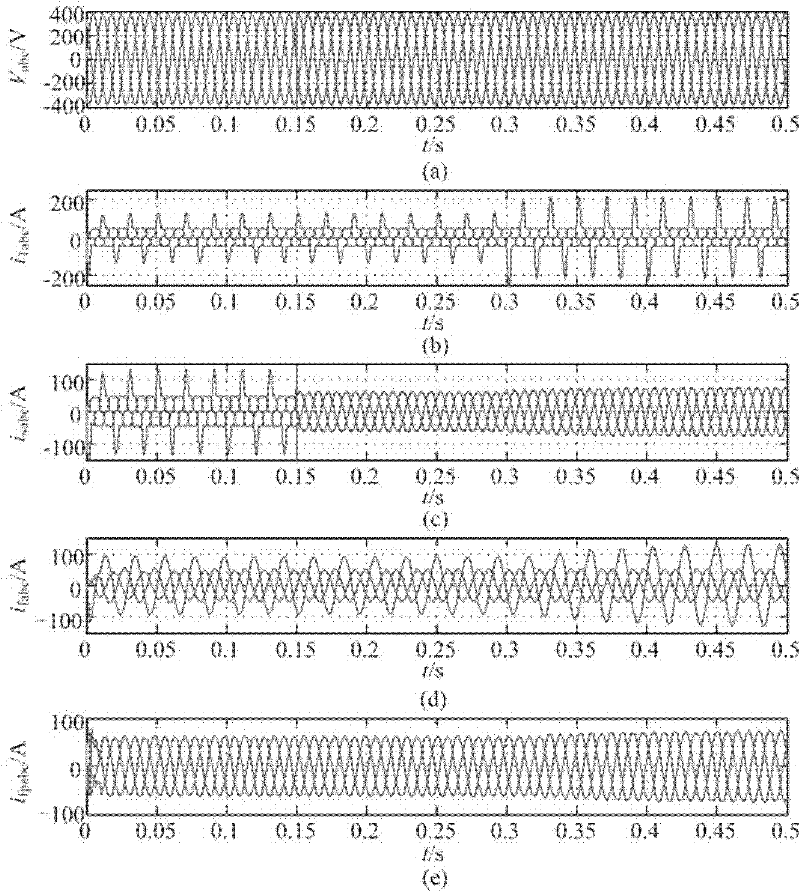
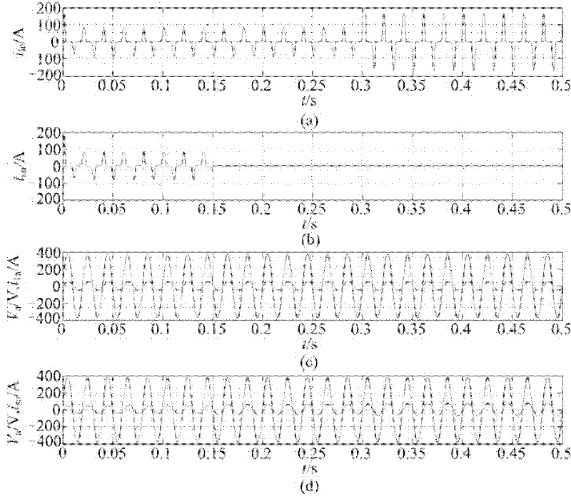
[0152] Ideally balanced mains voltage situation: figure 2 with image 3 The simulation results of the system in the case of ideal symmetrical three-phase sinusoidal mains voltage are shown. figure 2 The main voltage waveform V is given in abc (a), load current waveform i labc (b), power supply current waveform i sabc (c), the fundamental waveform i of the power supply current of each phase output by the two-dimensional linear filter fabc (d) and the waveform i of the positive sequence component of the current fundamental wave after the calculation of the symmetrical component fpabc (e). image 3 The compensation situation of neutral current and reactive current is given. Neutral current iln(a) before compensation, neutral current isn(b) after compensation, waveform Vsa, ila(c) of phase A voltage and current before compensation, voltage and current waveform Vsa, isa(d) after compensation. Table 2 shows the load current, power supply current, neutral current and their h...
Embodiment 2
[0157] Unbalanced sinusoidal mains voltage case: The unbalanced sinusoidal mains voltage is given by:
[0158] v a =380sinωt+38sinωt
[0159] v b =380sin(ωt-120°)+38sin(ωt+120°)
[0160] v c =380sin(ωt+120°)+38sin(ωt-120°)
[0161] The simulation results of the system in the case of unbalanced three-phase sinusoidal main voltage are as follows: Figure 4 with Figure 5 As shown, the meaning of each waveform in the figure is the same as figure 2 with image 3 same.
[0162] The simulation results show that under the action of unbalanced sinusoidal voltage, the load currents of A, B, and C phases are seriously unbalanced, and large harmonic currents appear on the neutral line. When the AFP is connected at 0.15s, the three-phase power supply current reaches balance, and the THD of the B-phase current drops from 39.34% to 1.14% between 0.15s and 0.3s. After the time is greater than 0.3s, the THD changes from the original 51.55% dropped to 1.27%, at the same time, the ne...
Embodiment 3
[0167] Balanced distorted main voltage situation: In order to study the system performance under balanced distorted main voltage, the following three-phase power supply is constructed:
[0168] v a =380sinωt+4.56sin3ωt+22.8sin(5ωt-120°)+5.7sin7ωt+3.8sin(11ωt-120°)
[0169] v b =380sin(ωt-120°)+4.56sin3ωt+22.8sin5ωt+5.7sin(7ωt-120°)+3.8sin11ωt
[0170] v c =380sin(ωt+120°)+4.56sin3ωt+22.8sin(5ωt+120°)+5.7sin(7ωt+120°)+3.8sin(11ωt+120°)
[0171] The simulation results of the system in the case of unbalanced three-phase sinusoidal main voltage are as follows: Image 6 with Figure 7 As shown, the meaning of each waveform in the figure is the same as figure 2 with image 3 same.
[0172] The simulation results show that under the action of the balanced and distorted main voltage, the load current and the power supply current are severely distorted and unbalanced, and the THD of the neutral current is 70.81%. It is well suppressed, the imbalance is compensated, and the ne...
PUM
 Abstract
Description
Claims
Application Information
 - R&D
- Intellectual Property
- Life Sciences
- Materials
- Tech Scout
- Unparalleled Data Quality
- Higher Quality Content
- 60% Fewer Hallucinations
Browse by: Latest US Patents, China's latest patents, Technical Efficacy Thesaurus, Application Domain, Technology Topic, Popular Technical Reports.
© 2025 PatSnap. All rights reserved.Legal|Privacy policy|Modern Slavery Act Transparency Statement|Sitemap|About US| Contact US: help@patsnap.com


