Short focus large-frame image equal scale optical correction method

A scale and large-format technology, which is applied in aerospace image measurement and aviation fields, can solve the problems of small object image space, artificial deformation, and affecting image resolution, etc., and achieve the effect of small image shadow loss and convenient operation

Inactive Publication Date: 2011-11-23
PLA AIR FORCE AVIATION UNIVERSITY
View PDF3 Cites 2 Cited by
  • Summary
  • Abstract
  • Description
  • Claims
  • Application Information

AI Technical Summary

Problems solved by technology

Most of the current image correction uses digital methods for computer correction. For computer correction, the process of film correction is very complicated: first, the film image must be digitized to become a digital image, and then the digital image is corrected. The corrected image output as photo
In the whole process, the image information will be lost many times. When the film image is digitally converted, a certain amount of shadow texture will be lost. After the image is corrected, a certain amount of shadow texture will be lost, and a certain amount of shadow texture will be lost when the image is output into a photo.
It affects the resolution of the image; when digital image is corrected, because it is an artificial image deformation, the degree of image deformation is related to the level of the programmer, and a certain amount of artificial deformation will occur
There is still no good method for optical correction, especially for images imaged by cameras with short focal lengths. Because the focal length is very short and the object image space is small, it is difficult to achieve image scale correction

Method used


Image

  • Short focus large-frame image equal scale optical correction method
  • Short focus large-frame image equal scale optical correction method
  • Short focus large-frame image equal scale optical correction method

Examples


Embodiment Construction

[0025] The steps of the present invention are:

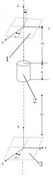
[0026] a. Determine the inclination angle between the aerial image and the vertical ground with pitch, roll, and yaw angles;

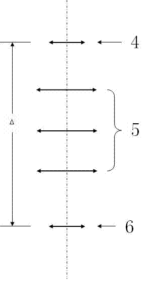
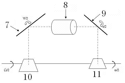
[0027] b. The film is imaged at the center of the correction lens I and the correction lens II, and the image is then imaged on the photo paper through the correction lens II;

[0028] d. The scale of each point on the corrected photo is a vertical scale;

[0029] e. The light source of the optical path adopts a surface light source, and the three-degree-of-freedom control of the film and photo paper is a three-degree-of-freedom platform;

[0030] f. Roll angle correction: The imaging film is placed according to the vertical plane setting angle with the main optical axis of the imaging. After correcting the lens imaging, the target on the apogee film is closer to the lens, and the image magnification at this point is larger. If the target on the perigee film is far away from the lens, the magnification...


PUM


Abstract

The invention discloses a short focus large-frame image equal scale optical correction method, which belongs to the aviation and navigation image measurement field. The purpose of the invention is to provide a short focus large-frame image equal scale optical correction method for the optical correction of a film image and a digital image while outputting the images. An inclination between the aviation image and the vertical ground is determined according to a pitch angle, a roll angle and a yaw angle; a photographic film is imaged at a central position of a correction lens I and a correctionlens II, the scale of each point on the photograph after the correction is a vertical scale; the three-degree-of-freedom control of the photographic film and photographic paper is realized by a three-degree-of-freedom platform; the photographic film is arranged according to a perpendicular set angle with an imaging main optical shaft, pitch correction is same as roll correction; the roll correction and the pitch correction are carried out on a two-degree-of-freedom platform to ensure that image deformation caused by two postures can be corrected, thus a positive shot image is formed. By usingthe optical correction method, man-made image deformation cannot be caused. The equal scale (the ratio of photographic films to photos is 1: 1) can be realized.

Description

technical field [0001] The invention belongs to the field of aviation and aerospace image measurement. Background technique [0002] Due to the instability of the carrier during the acquisition of aviation and aerospace images, the image is not completely vertical, forming inclination angles such as pitch, roll, and yaw, which makes the scales of each point different, which affects aerial measurement. This has to be corrected so that the scale is the same at all points of the image. Most of the current image correction uses digital methods for computer correction. For computer correction, the process of film correction is very complicated: first, the film image must be digitized to become a digital image, and then the digital image is corrected. The corrected image Then output it as a photo. During the whole process, the image information will be lost many times. A certain amount of shadow texture will be lost when the film image is digitally converted, a certain amount of...

Claims


Application Information

Patent Timeline
Patent Type & Authority Applications(China)
IPC IPC(8): G03B17/32G01C11/02
Inventor 郭永胜刘宇邓长春沙宇芳孙文邦
Owner PLA AIR FORCE AVIATION UNIVERSITY
Why Eureka
Try Eureka