Short-circuit current limiter additionally-arranging method and device

A short-circuit current limiting and short-circuit current technology, applied in circuit devices, emergency protection circuit devices, emergency protection circuit devices for limiting overcurrent/overvoltage, etc. Find out the installation configuration of the current limiter and the inability to comprehensively consider the effect of limiting the short-circuit current of the large power grid.

Active Publication Date: 2011-11-23
ELECTRIC POWER RES INST OF GUANGDONG POWER GRID
View PDF2 Cites 11 Cited by
  • Summary
  • Abstract
  • Description
  • Claims
  • Application Information

AI Technical Summary

Problems solved by technology

[0004] However, the current limiter installation configuration mainly depends on engineering experience and manual selection. The analysis process and results lack effective evaluation indicators for the short-circuit current limiting effect, and it is impossible to comprehensively consider the overall short-circuit current limiting effect of the large power grid. When the distribution of short-circuit current limit nodes is wide, the traditional engineering experience selection work will become very complicated and cumbersome, and it is impossible to accurately find out the global optimal current limiter installation configuration

Method used


Image

  • Short-circuit current limiter additionally-arranging method and device
  • Short-circuit current limiter additionally-arranging method and device
  • Short-circuit current limiter additionally-arranging method and device

Examples


Embodiment Construction

[0028] In order to facilitate the understanding of the present invention, the following will be described in conjunction with the accompanying drawings.

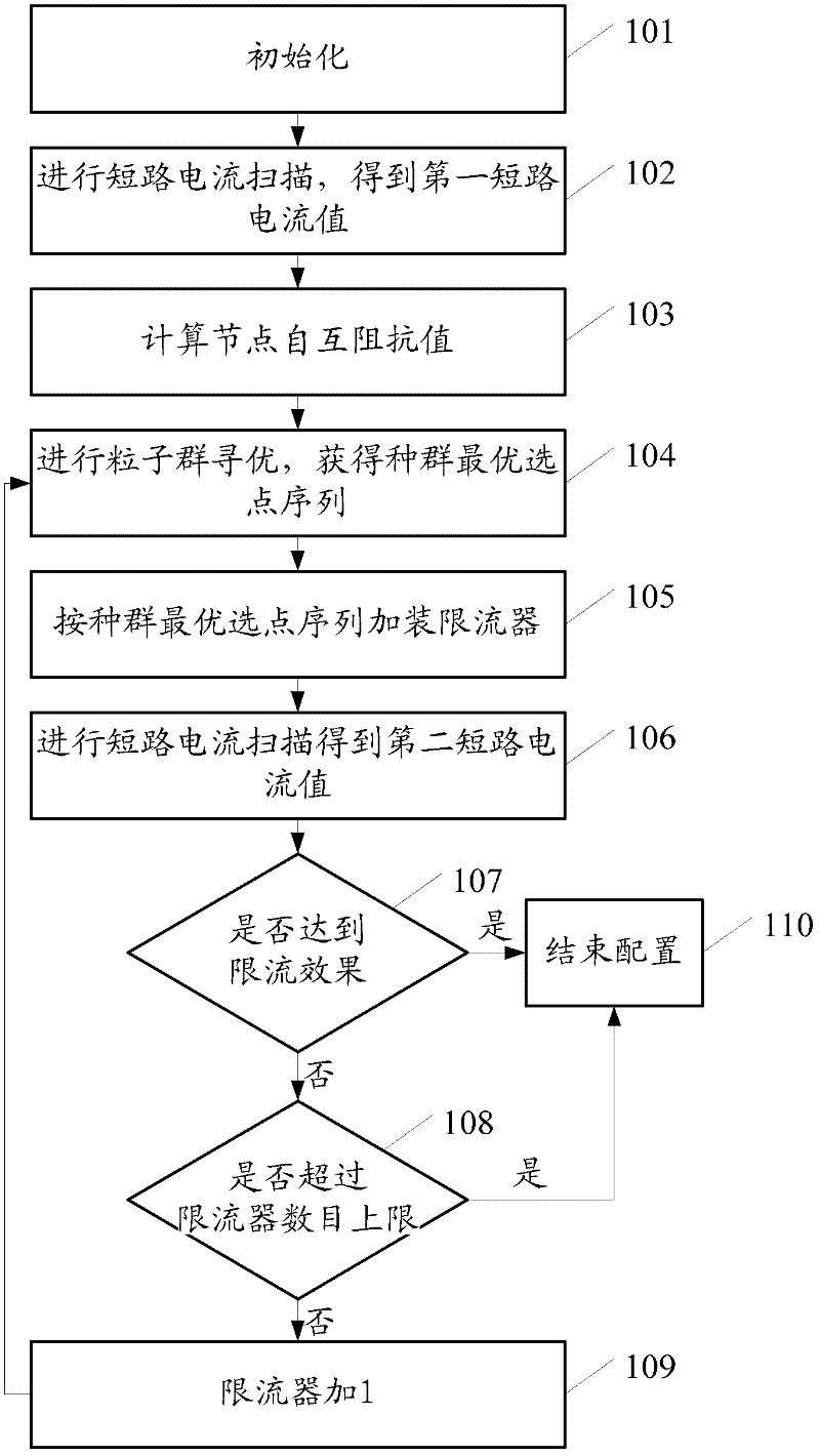
[0029] refer to figure 1 , first introduce the method of the present invention, a method for installing and configuring a short-circuit current limiter, comprising steps:

[0030] 101. Initialize;

[0031] The upper limit of the number of current limiters that can be installed, the theoretical current limit target, and the current number of current limiters are set to 1 in advance.

[0032] 102. Perform short-circuit current scanning to obtain the first short-circuit current value;

[0033] A short-circuit current scan is performed on each designated voltage level node to obtain a first short-circuit current value of each designated voltage level node.

[0034] 103. Calculate the node self-transimpedance value;

[0035] Determining the voltage level nodes that need to be limited by short-circuit current according to the ...


PUM


Abstract

The invention discloses a short-circuit current limiter additionally-arranging method which comprises the steps of: presetting an upper limit of the number of current limiters, a theoretical current-limiting target and the number of current additionally-arranging current limiters; scanning short circuit current; determining nodes needing limiting; calculating mutual impedance values of the nodes; carrying out particle swarm optimization to obtain corresponding selected node sequences; configuring the current limiters according to the selected node sequences; re-scanning the short circuit current; calculating an actual current-limiting target, if the actual current-limiting target is within a range of the theoretical current-limiting target, ending; if the actual current-limiting target is not within the range of the theoretical current-limiting target and the number of the arranged current limiter does not exceed the upper limit, adding 1 and continuously carrying out particle swarm optimization; and if the actual current-limiting target is not within the range of the theoretical current-limiting target and the number of the arranged current limiter exceeds the upper limit, ending. The invention also discloses a configuring device. A global optimum additionally-arranging configuration point of a short circuit current limiter can be rapidly and accurately found.

Description

technical field [0001] The invention relates to the field of power system analysis, in particular to a method and device for installing and configuring a short-circuit current limiter. Background technique [0002] With the rapid development of the power system, the scale of the power grid continues to expand, and the degree of interconnection between large power grids is getting closer, the level of short-circuit current in the power grid continues to rise, which greatly affects the safe and stable operation of the power grid, and the power grid has to sacrifice power supply reliability for partitioning and stratification run. How to limit the short-circuit current has become the most prominent problem in the operation of the power grid in recent years, and it is one of the main bottlenecks restricting the further development of the power grid. [0003] Using a current limiter is one of the main ways to limit short-circuit current at present. It can effectively alleviate t...

Claims


Application Information

Patent Timeline
Patent Type & Authority Applications(China)
IPC IPC(8): H02H9/02
Inventor 孙闻陈迅王建全应林志
Owner ELECTRIC POWER RES INST OF GUANGDONG POWER GRID
Why Eureka
Try Eureka