Stamping equipment and control method for stamping equipment
A technology of stamping equipment and a control method, which is applied in the field of stamping equipment and the control of stamping equipment, can solve the problems of large-scale stamping equipment and increased energy consumption, and achieve the effects of suppressing energy consumption, improving ejection ability, and promoting rotation
- Summary
- Abstract
- Description
- Claims
- Application Information
AI Technical Summary
Problems solved by technology
Method used
Image
Examples
no. 1 approach 〕
[0042] Hereinafter, a first embodiment of the present invention will be described with reference to the drawings. It should be noted that, in the second embodiment and onwards described later, the same components and components having the same functions as those in the first embodiment described below are assigned the same reference numerals, and the description thereof will be simplified or omitted.
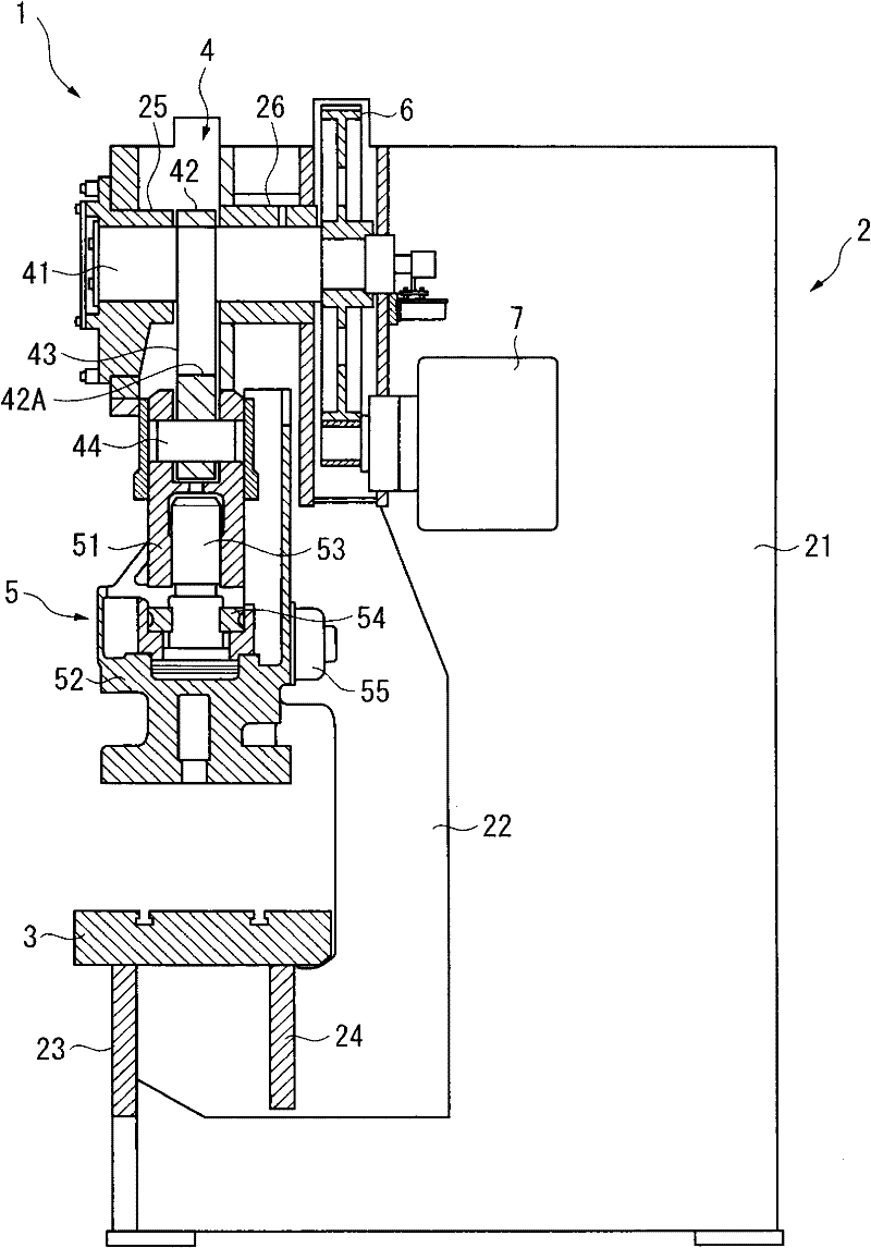
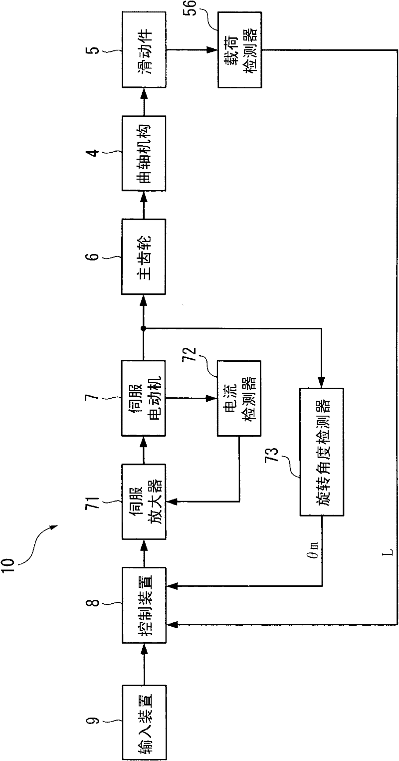
[0043] exist figure 1 Among them, the stamping equipment 1 has: a main body frame 2 composed of a plurality of plate-shaped frame members; a backing plate 3 arranged on the front side of the lower part of the main body frame 2; a crank mechanism 4 arranged on the upper part of the main body frame 2; 4 slider 5 connected freely up and down; servo motor 7 as a motor that drives crank mechanism 4 via main gear 6; figure 2 reference).
[0044] The main body frame 2 is provided with a pair of vertical plate-shaped frames 21 forming both sides and a thick-plate-shaped slider suppor...
no. 2 approach 〕
[0086] Next, according to Image 6 and Figure 7 A second embodiment of the present invention will be described.
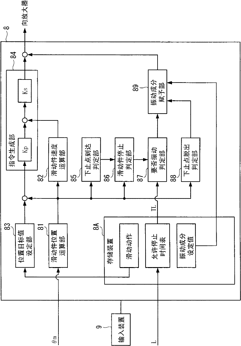
[0087] In the first embodiment described above, the allowable stop time TL of the slider 5 corresponding to the load L is read from the allowable stop time table stored in the storage device 8A, and when the stop time T of the slider 5 is within the allowable stop time TL In the above case, a vibration component is given to the control command of the servo amplifier 71 .
[0088] On the other hand, in the second embodiment, the allowable stop time table is not used in the determination of the necessity of the vibration component, and the vibration component is given when the stop time T of the slider 5 is equal to or greater than the allowable stop time TA at the time of the maximum load. , which is different.
[0089] That is, if Image 6 As shown, the bottom dead center release device 10 of this embodiment does not include the load detector 56 . In addition...
no. 3 approach 〕
[0098] Next, according to Figure 9 and Figure 10 A third embodiment of the present invention will be described.
[0099] In the first embodiment described above, the stop time T of the slider 5 is calculated, and when the stop time T exceeds the allowable stop time TL corresponding to the load L of the slider 5, a vibration component is given to the control command of the servo amplifier 71. .
[0100] On the other hand, in the third embodiment, whether or not it is necessary is determined from the relationship between the scheduled stop time TB of the slider 5 obtained from the sliding operation, the allowable stop time TL corresponding to the load L, and the allowable stop time TA at the time of the maximum load. The imparting of vibration components is different in this point.
[0101] Specifically, as Figure 9 As shown, the necessary vibration determination unit 87 of the control device 8 reads the allowable stop time TL of the slider 5 corresponding to the load L f...
PUM
 Abstract
Description
Claims
Application Information
 - R&D
- Intellectual Property
- Life Sciences
- Materials
- Tech Scout
- Unparalleled Data Quality
- Higher Quality Content
- 60% Fewer Hallucinations
Browse by: Latest US Patents, China's latest patents, Technical Efficacy Thesaurus, Application Domain, Technology Topic, Popular Technical Reports.
© 2025 PatSnap. All rights reserved.Legal|Privacy policy|Modern Slavery Act Transparency Statement|Sitemap|About US| Contact US: help@patsnap.com


