Endless belt and method for manufacturing same

A manufacturing method and technology of endless belts, applied in chemical instruments and methods, belts, closed-loop articles, etc., can solve problems such as difficulty in producing a thin surface layer with a thickness

Inactive Publication Date: 2007-11-21
SUMITOMO ELECTRIC FINE POLYMER INC
View PDF1 Cites 2 Cited by
  • Summary
  • Abstract
  • Description
  • Claims
  • Application Information

AI Technical Summary

Problems solved by technology

However, only transfer belts for image forming apparatuses having a small diameter (less than 100 mm) can be produced
In addition, it is difficult to produce thin surface layers with a thickness of less than 30 microns

Method used


Image

  • Endless belt and method for manufacturing same
  • Endless belt and method for manufacturing same
  • Endless belt and method for manufacturing same

Examples


no. 1 example

[0097] In this embodiment, a composite body including an elastic layer provided on the outside of the base layer is inserted inside the surface layer, and the core is used to bond the surface layer and the elastic layer.

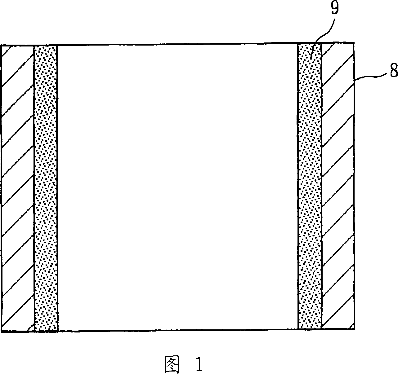
[0098] As shown in FIG. 1, PTFE (melting point: 327° C., thermal decomposition temperature: 400° C.) is applied to the inner surface of an outer cylinder 8 having a mirror surface by dipping, and baked at 380° C. polished inner surface and has a coefficient of thermal expansion of 1.76 x 10 -5 / ℃ steel (stainless steel) composition.

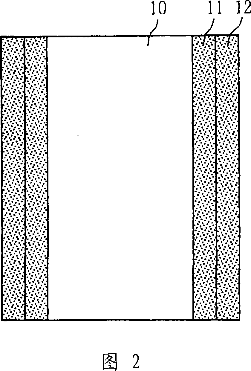
[0099] As shown in FIG. 2, the surface of the drum mold 10 is treated with carbon for conduction. Polyimide having adjusted volume resistivity was formed thereon and baked at 380° C. to form base layer 11 . Aqueous polyurethane (melting point: 120° C., thermal decomposition temperature: 180° C.) imparting ion conductivity was applied on base layer 11 by dipping and dried to form elastic layer 12 . The ion conductivity treat...

no. 2 example

[0105] Tightly bond the surface layer to the elastic layer without leakage. In this embodiment, the elastic layer is formed on the inner surface of the surface layer composed of fluoropolymer. The base layer is bonded to the inner surface of the elastic layer by thermal bonding. The surface layer is further tightly bonded to the elastic layer by thermal bonding.

[0106] In the same manner as in the first embodiment, PFA (350J dispersion manufactured by E, I, Du Pont de Nemours & Company Inc., particle diameter: 0.2 µm) (melting point: 295° C.) was applied to the outer cylinder 8 by dipping. The inner surface is baked at 380°C to form a surface layer, wherein the cylinder 8 has a mirror-polished inner surface and has a coefficient of thermal expansion of 1.76×10 -5 / ℃ steel composition.

[0107] Apply an adhesion-improving treatment to the inner surface of the surface layer, such as plasma treatment or radical treatment. By dipping, polyurethane (melting point: 120° C., t...

no. 3 example

[0118] In this example, the fluoropolymer constituting the surface layer consisted of 70 parts of PFA and 30 parts of PTEE. The complex was produced as in the first example. Water pockets are employed to bind the surface layer and complex.

[0119] First, the device will be described.

[0120] The bonding of the surface layer and the composite is described with reference to FIGS. 7 and 8 . Fig. 7 shows the whole water bag 50, the middle part 51 marked by the solid line of the water bag, the middle part 52 when the diameter marked by the dotted line increases, the end plate (panel) 55, the pump 59, the end plate (panel) that is arranged on the upper and lower ends of the middle part, A vacuum chamber 60 , a cover 61 of the vacuum chamber and a vacuum pump 62 . FIG. 8 shows a detachable electric heater 70 .

[0121] The water bag 50 is a liquid container as a whole. The middle part 51 is made of silicone rubber. Thus, as shown in FIG. 7 , the intermediate portion 51 can be...


PUM

PropertyMeasurementUnit
diameteraaaaaaaaaa
thicknessaaaaaaaaaa
thicknessaaaaaaaaaa

Abstract

There are provided an endless belt having a structure containing at least three layers, a middle layer being disposed between the outermost layer and a bottom layer, and the middle layer being composed of a material having a thermal decomposition temperature lower than the deposition temperature of each of the outermost layer and the bottom layer, and provided a method for manufacturing the endless belt. There are provided an endless belt having high surface resistivity, an excellent toner releasing property, an excellent non-contaminated property, stable volume resistivity, excellent adhesion between a surface layer and an elastic layer, and the like without the occurrence of disadvantageous bleeding of a contaminant, and a method for manufacturing the endless belt.

Description

technical field [0001] The present invention relates to an endless belt and a method of manufacturing the same. In particular, the present invention relates to an endless belt for an image forming apparatus, such as a color copier or a color laser printer using an electrophotographic method, for transferring and fixing a toner image on a photosensitive drum to a on paper. The invention also relates to a method of manufacturing the endless belt. Background technique [0002] Endless belts are used in different fields. For example, as a method of transferring and fixing an image in a color image forming apparatus such as a color copier and a color laser printer, a method in which a toner image formed on a photosensitive drum passes through a ring for the image forming apparatus is used. The tape (hereinafter simply referred to as "belt", especially in the background art), is transferred and fixed on paper or the like. The above approach is becoming the standard approach. ...

Claims


Application Information

Patent Timeline
Patent Type & Authority Applications(China)
IPC IPC(8): G03G15/16G03G15/20G03G15/00
CPCB32B27/34B32B27/322B32B37/10B32B27/08B32B2413/00B32B25/08B32B2327/18B29D29/00B32B25/14B32B27/304B29L2009/00B32B2309/105B32B25/20B32B2274/00B32B2307/51B32B2433/00G03G15/162B32B27/40B32B27/281B32B2375/00G03G15/14
Inventor 池田一秋
Owner SUMITOMO ELECTRIC FINE POLYMER INC
Why Eureka
Try Eureka