
Brake pads for high-speed train braking systems

A brake system and technology for high-speed trains, applied to friction linings, mechanical equipment, etc., can solve problems such as brake failure of high-speed trains, multiple accidents of high-speed trains, partial friction of brake pad friction blocks, etc., to achieve uniform force, improve Operational efficiency, thermal crack reduction effect

Inactive Publication Date: 2011-11-30
MIN OF RAILWAY TRANSPORT BUREAU +1
View PDF6 Cites 7 Cited by
  • Summary
  • Abstract
  • Description
  • Claims
  • Application Information

AI Technical Summary

Problems solved by technology

[0005] The problem caused by the copper-based powder metallurgy high-speed brake pads in the above-mentioned patent application is that it is difficult for the brake pads to withstand the harsh working conditions of the combined action of large thermal load and alternating stress during the braking process of high-speed trains, and it is easy to make the brake pads The friction block produces partial friction and other adverse phenomena
In the actual train operation, defects such as the falling of the friction block of the brake pads and partial friction can cause the brake failure or accelerated failure of the high-speed train, which not only wastes costs, but also leads to more accidents in high-speed trains.

Method used


Image

  • Brake pads for high-speed train braking systems
  • Brake pads for high-speed train braking systems
  • Brake pads for high-speed train braking systems

Examples


Embodiment Construction

[0020] In order to make the purpose, technical solutions and advantages of the present invention clearer, the technical solutions in the embodiments of the present invention will be clearly and completely described below in conjunction with the accompanying drawings in the embodiments of the present invention. Obviously, the described embodiments are the Some, but not all, embodiments are invented. Based on the embodiments of the present invention, all other embodiments obtained by persons of ordinary skill in the art without creative efforts fall within the protection scope of the present invention.

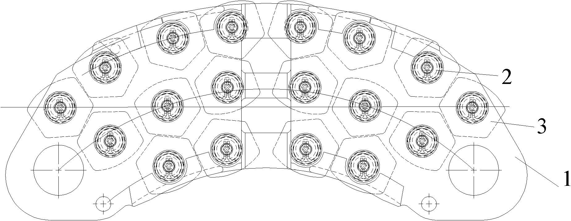
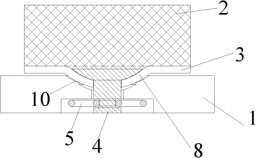
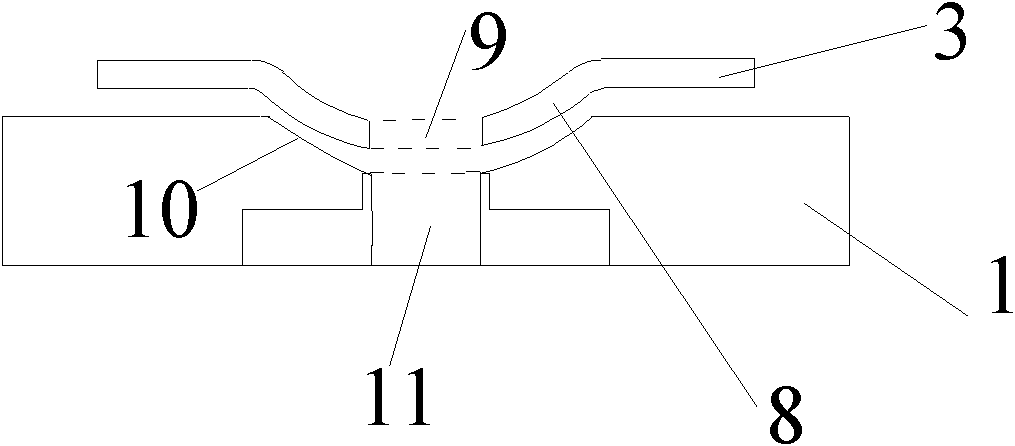
[0021] refer to figure 1 , Figure 2A and Figure 2B as shown, figure 1 A schematic structural view showing an embodiment of a brake pad for a high-speed train braking system in the present invention; Figure 2A A cross-sectional view showing an embodiment of a brake pad for a high-speed train braking system in the present invention; Figure 2B A partial cross-sectional vie...


PUM


Abstract

The invention discloses a brake pad for a high-speed train braking system, which comprises: a first steel back with an integral structure, and more than one spaced apart friction blocks are arranged above the first steel back; each friction block and the A second steel back is arranged between the first steel backs, and the middle area of ​​the second steel back has a raised portion facing the first steel back; hole, and a concave part is provided on the side of the first steel back that contacts the second steel back, and the concave part is matched with the raised part, and the fixed pin is provided on the concave part to freely pass through the first steel back. The first installation hole of the back; on the side of the first steel back and away from the second steel back, there is a snap ring that snaps onto the other end of the fixing pin, and the snap ring is located on the first steel back Inside. The above-mentioned brake pads can withstand relatively high thermal loads, and can reduce the eccentric wear phenomenon of the friction blocks in the brake pads, so that the friction surfaces of the corresponding brake discs are evenly stressed, and the braking efficiency is improved.

Description

technical field [0001] The invention relates to a disc brake device, in particular to a brake pad for a high-speed train braking system. Background technique [0002] The trains in the existing railway system are all equipped with a braking system. The executive unit of the common high-speed train braking system, namely the braking device, includes a brake disc and a brake pad, which are respectively arranged on the high-speed train. The wheels of each compartment are structured so as to receive braking commands from the braking system to generate braking force on the wheels. [0003] However, as the running speed of the train increases, its kinetic energy increases sharply, and the brake discs and brake pads of the braking system generate a large amount of heat during braking. In the prior art, the heat can only be dissipated through the heat transfer of the brake discs. , thus making the brake discs and brake pads of the braking device extremely vulnerable to damage, resu...

Claims


Application Information

Patent Timeline
Patent Type & Authority Applications(China)
IPC IPC(8): F16D69/04
Inventor 李继山李和平焦标强韩晓辉
Owner MIN OF RAILWAY TRANSPORT BUREAU
Learn More