A swirl burner

A technology of swirl burner and stable burner, which is applied in the direction of burner, combustion method, combustion type, etc., and can solve the deviation of smoke temperature and flow rate in horizontal flue, obstacles to reliable operation of superheater and reheater, and slagging in the furnace and furnace water-cooled wall tube high-temperature corrosion and other problems, to achieve the effect of stable combustion

Inactive Publication Date: 2011-11-30
大连经济技术开发区水国燃烧器有限公司
View PDF0 Cites 7 Cited by
  • Summary
  • Abstract
  • Description
  • Claims
  • Application Information

AI Technical Summary

Problems solved by technology

[0002] The burner in the traditional technology is easy to cause slagging in the furnace and high temperature corrosion of the furnace water wall tube
The residual rotation of the gas flow at the furnace outlet will cause serious deviations in the gas temperature and flow rate on the left and right sides of the horizontal flue, which will become an obstacle to the reliable operation of the superheater and reheater

Method used


Image

  • A swirl burner
  • A swirl burner

Examples


Embodiment Construction

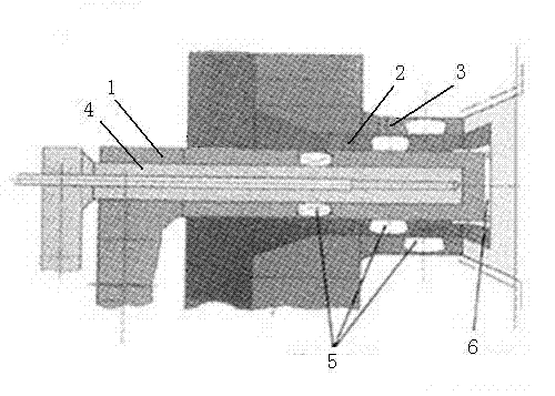
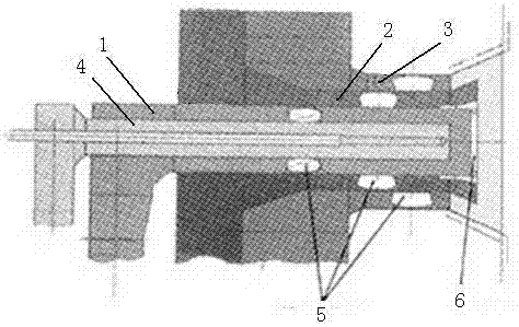
[0008] Such as figure 1 As shown, a swirl burner includes a primary air channel 1, an inner secondary air channel 2, an outer secondary air channel 3 and a central air channel 4, and the inner secondary air channel 2 and the outer secondary air channel 3 connection, the primary air channel 1 is installed in the inner secondary air channel 2, the central air channel 4 is installed in the primary air channel 1, and the tooth ring stabilizer 6 is installed on the primary air channel 1 , the primary air channel 1 is equipped with swirl vanes 5 , the inner secondary air channel 2 is equipped with swirl vanes 5 , and the outer secondary air channel 3 is equipped with swirl vanes 5 .

[0009] The end of the central air channel 4 adopts a straight structure, the end of the primary air channel 1 is equipped with an expanded cone, and the ends of the inner secondary air channel 2 and the outer secondary air channel 3 are also externally expanded, and the externally expanded secondary A...


PUM


Abstract

The invention discloses a swirl burner, comprising a primary air passage, an inner secondary air passage, an outer secondary air passage and a central air passage, wherein the inner secondary air passage is connected with the outer secondary air passage, and the The inner secondary air channel is equipped with a primary air channel, the primary air channel is equipped with a central air channel, the primary air channel is equipped with a tooth ring burner, and the primary air channel is equipped with a swirl flow Blades, the inner secondary air channel is equipped with swirl blades, and the outer secondary air channel is equipped with swirl blades. The invention can form a stable backflow area, which is beneficial to the ignition of pulverized coal, the internal and external secondary air diffuses outward, and will not participate in the ignition process of pulverized coal, and the ignition heat required by the pulverized coal airflow can be reduced to a minimum, even if anthracite is used. Stable combustion.

Description

technical field [0001] The invention relates to a swirl burner. Background technique [0002] The burner in the traditional technology is easy to cause slagging in the furnace and high temperature corrosion of the furnace water wall tube. The residual rotation of the gas flow at the furnace outlet will cause serious deviations in the flue gas temperature and flow rate on the left and right sides of the horizontal flue, which will become an obstacle to the reliable operation of the superheater and reheater. Contents of the invention [0003] The object of the present invention is to overcome the above-mentioned deficiencies and provide a swirl burner. [0004] The technical solution adopted by the present invention to achieve the above object is: a swirl burner, including a primary air channel, an inner secondary air channel, an outer secondary air channel and a central air channel, the inner secondary air channel and the The outer secondary air channel is connected, the ...

Claims


Application Information

Patent Timeline
Patent Type & Authority Applications(China)
IPC IPC(8): F23D1/02
Inventor 韩义全
Owner 大连经济技术开发区水国燃烧器有限公司
Why Eureka
Try Eureka