
display module

A display module and display panel technology, applied in the direction of instruments, identification devices, etc., can solve the problems of occupying the layout space of the system board, increasing the thickness of electronic products, increasing the assembly process and difficulty of display module assembly, and reducing the cost of pressing The number of times, to avoid the effect of thickness increase

Inactive Publication Date: 2011-11-30
AU OPTRONICS (SUZHOU) CORP LTD +1
View PDF5 Cites 2 Cited by
  • Summary
  • Abstract
  • Description
  • Claims
  • Application Information

AI Technical Summary

Problems solved by technology

[0005] However, in the above-mentioned arrangement of the circuit board module, it is necessary to perform pressing action between the rigid circuit board and the flexible circuit board and between the display panel and the flexible circuit board, which increases the assembly process and difficulty of the display module.
Moreover, in the above arrangement method, when a rigid circuit board is arranged on the bottom side of the plastic frame, the rigid circuit board usually occupies the layout space of the system board, which may increase the thickness of the electronic product, which is inconsistent with the trend of thinning electronic products

Method used


Image

  • display module
  • display module
  • display module

Examples


Embodiment Construction

[0031] In order to further explain the technical means and effects of the present invention to achieve the intended purpose of the invention, the specific implementation, structure, features and effects of the display module proposed according to the present invention will be described in detail below in conjunction with the accompanying drawings and preferred embodiments. The description is as follows.

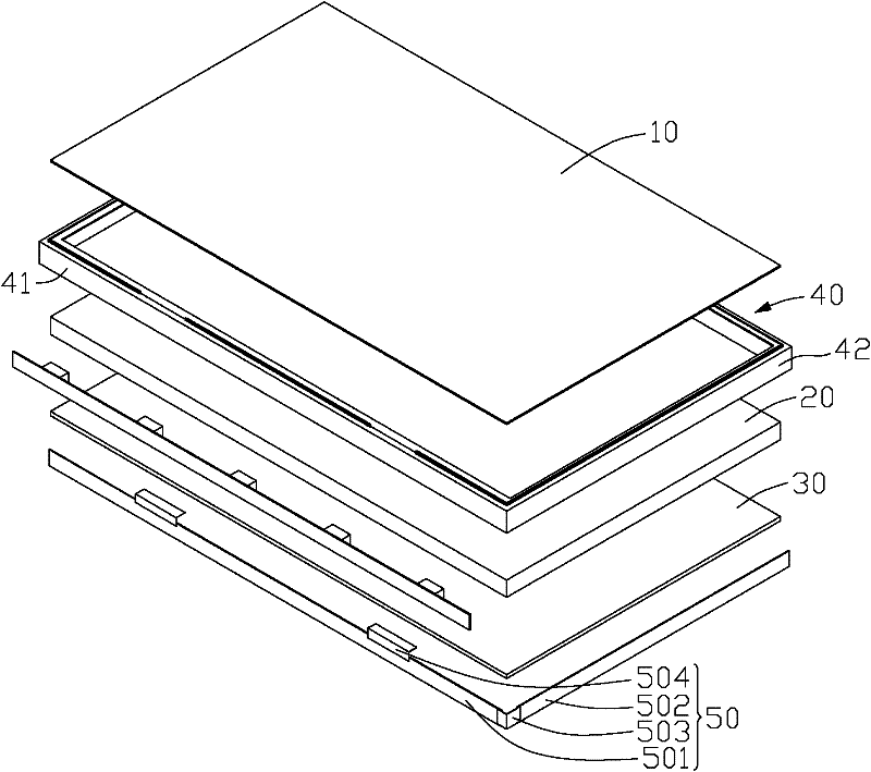
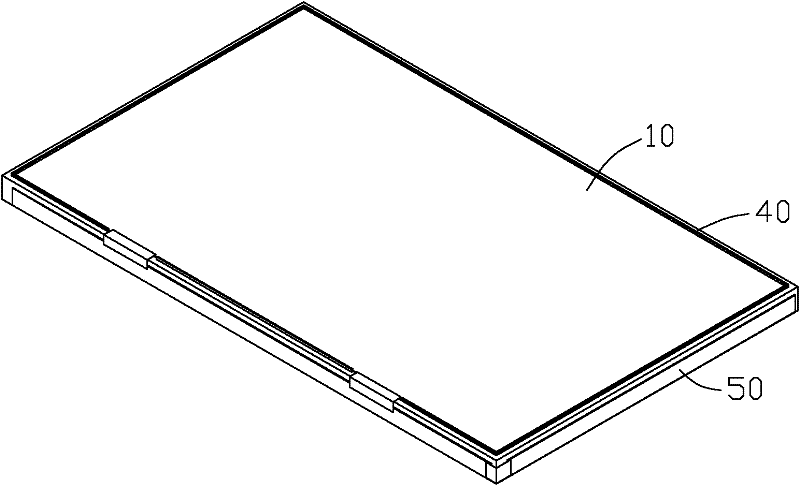
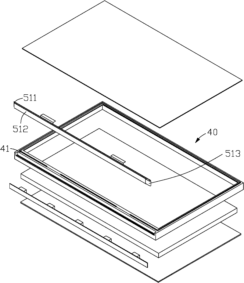
[0032] figure 1 and figure 2 Shown is a schematic diagram of the first embodiment of the display module of the present invention. Such as figure 1 and figure 2 As shown, the display module of the embodiment of the present invention includes a display panel 10 , an optical film set 20 , a backplane 30 , a plastic frame 40 and a rigid-flex circuit board 50 .

[0033] The plastic frame 40 is roughly rectangular to match the shape of the display panel 10 , and can be used to fix the display panel 10 , the optical film set 20 and the backplane 30 . The display panel 10 and ...


PUM


Abstract

The invention provides a display module. The display module comprises a display panel, an optical membrane group, a backboard, a glue frame and a rigid-flexible combination circuit board. The optical membrane group is arranged between the display panel and the backboard and the glue frame is used for fixing the optical membrane group. The rigid-flexible combination circuit board comprises a first rigid area, a second rigid area, a flexible area which is electrically connected between the first rigid area and the second rigid area, and a flexible connection part; the first rigid area is electrically connected with the display panel through the flexible connection part to establish an electric connection between the rigid-flexible combination circuit board and the display panel; and the first rigid area and the second rigid area are respectively distributed at different sides of the glue frame or are overlapped at the same side of the glue frame. The display module provided by the invention supplies flexible and various circuit board placing ways through utilizing the rigid-flexible combination circuit board so that the advantages of reducing assembling flow and reducing assembly difficulty and / or reducing the thickness of the display module and conveniently laminating can be realized.

Description

technical field [0001] The present invention relates to an electronic device, in particular to a display module of the electronic device. Background technique [0002] With people's requirements for thinner and lighter electronic products, the internal space of electronic products is getting smaller and smaller. As an important component of electronic products, the thinning and lightening of display modules has also attracted the attention of the industry. [0003] Existing display modules usually include a display panel, an optical film set, a back plate and a frame. The display panel and the back plate are respectively fixed on the upper and lower sides of the frame. between the backplanes. In addition, in order to provide power, data and control signals for the above-mentioned display module, a circuit board module composed of a rigid circuit board and a flexible circuit board is usually required to be electrically connected to the display module. [0004] In view of t...

Claims


Application Information

Patent Timeline
IPC IPC(8): G09F9/00
Inventor 沈冬明程大伟
Owner AU OPTRONICS (SUZHOU) CORP LTD
Learn More