
Assembling method of guiding device and oil seal of damper

An assembly method and a technology of guides, which are applied in the direction of shock absorbers, springs/shock absorbers, shock absorbers, etc., can solve the problems of damage to the ring seal, affecting the assembly efficiency of the shock absorber, and the inability to realize the assembly method, etc.

Active Publication Date: 2021-08-17
青岛睿智森油封有限公司
View PDF9 Cites 0 Cited by
  • Summary
  • Abstract
  • Description
  • Claims
  • Application Information

AI Technical Summary

Problems solved by technology

The existing assembly method requires two positioning and press-fitting, which affects the assembly efficiency of the shock absorber
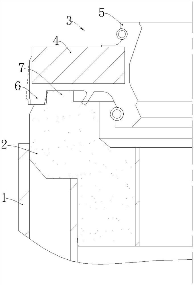
In order to improve efficiency, technicians have tried other assembly methods: 1. If the guider and the oil seal are installed as one, the annular sealing body will be stretched outward by the annular boss. At this time, because the outer diameter of the annular sealing body is larger than the outer Inner diameter of the barrel (see figure 1 middle dotted line), so it is difficult to install the guide and oil seal into the outer cylinder, and the annular sealing body will be damaged by the shear force at the end of the outer cylinder during installation
2. If the oil seal and the guide are pre-positioned first, that is, the part of the annular sealing body is sleeved outside the annular boss and an axial gap is left, the purpose is to integrate the oil seal and the guide without affecting the insertion into the outer cylinder. However, since the static friction force between the annular sealing body made of rubber and the annular boss made of metal is not enough to maintain the pre-positioned state of the two, this assembly method cannot be realized.

Method used


Image

  • Assembling method of guiding device and oil seal of damper
  • Assembling method of guiding device and oil seal of damper
  • Assembling method of guiding device and oil seal of damper

Examples


Embodiment 1

[0021] Figure 2-Figure 6 Embodiment 1 of the present invention is shown.

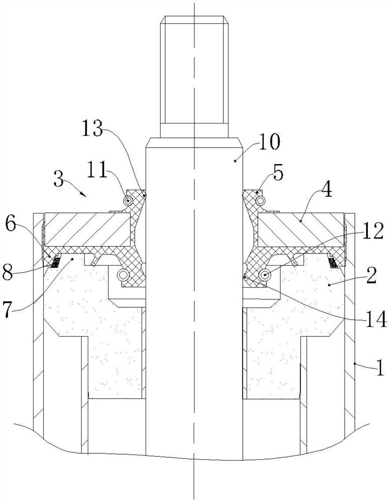
[0022] Such as figure 2 As shown, a shock absorber includes an outer cylinder 1 , a guide 2 , an oil seal 3 , an auxiliary mounting ring 8 , and a piston rod 10 . Both the guide 2 and the oil seal 3 are installed inside the outer cylinder 1 . The guide 2 and the oil seal 3 are sleeved on the outside of the piston rod 10 .

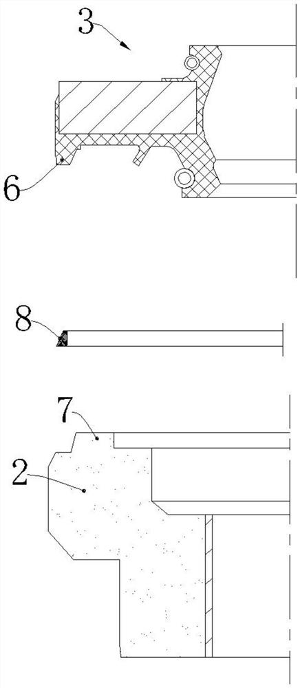
[0023] The oil seal 3 includes a metal frame 4 , a rubber body 5 , a first holding spring 11 , and a second holding spring 12 . The metal skeleton 4 and the rubber body 5 are vulcanized into one body, and the lower end of the rubber body 5 is provided with an annular sealing body 6, and the inner surface of the annular sealing body 6 is conical in shape with a small top and a large bottom.

[0024] The upper end of the guide 2 is provided with an annular boss 7, and the outer surface of the annular boss 7 is conical in shape with a small top and a big bottom.

[0025] The auxi...


PUM


Abstract

The invention relates to the technology of assembly of dampers, in particular to an assembling method of a guiding device and an oil seal of a damper. The assembling method comprises the following steps: A, mounting an auxiliary mounting ring on the outer part of an annular boss; B, pre-locating the oil seal and the guiding device, that is, a part of a annular sealing body is sleeved on the outer part of the auxiliary mounting ring and an axial gap is reserved between the annular sealing body and the guiding device; C, pressing the oil seal and the guiding device into an outer tube together, continuously applying pressure to the oil seal after the guiding device is located until the axial gap is eliminated, and ensuring that the annular sealing body is interference fit with the inner wall of the outer tube. According to the assembling method disclosed by the invention, through arrangement of the rubber-made auxiliary mounting ring and pre-location of the auxiliary guiding device and the oil seal, the press-fit times of the guiding device and the oil seal in an assembling process can be reduced, and the assembling efficiency of the damper is improved.

Description

technical field [0001] The invention relates to shock absorber assembly technology, in particular to an assembly method of a guide and an oil seal of the shock absorber. Background technique [0002] Hydraulic shock absorbers are widely used in automobile shock absorption systems. When the frame and the axle are reciprocating relative to each other, the piston (the piston rod is connected to the frame or the body) is in the cylinder of the shock absorber (the cylinder is connected to the axle) ) to move back and forth, and when the piston reciprocates in the cylinder, the oil in the housing will repeatedly flow from one inner cavity through some narrow pores into the other inner cavity. Due to the throttling effect of the small hole, at this time, the friction between the hole wall and the oil and the internal friction of the liquid molecules form a damping force on the vibration, so that the vibration energy of the body and frame is converted into heat energy, which is abso...

Claims


Application Information

Patent Timeline
IPC IPC(8): F16F9/36
CPCF16F9/362
Inventor 李芳郑德武刘燕芳
Owner 青岛睿智森油封有限公司
Learn More