Cylinder surface treatment device

A technology for surface treatment devices and cylinders, applied to sealing devices, cylinders, cylinder heads, etc., can solve the problems of increasing the supply cost and storage cost of cover parts 107, increasing the man-hours of changing cover parts 107, etc.

Inactive Publication Date: 2011-11-30
HONDA MOTOR CO LTD
View PDF3 Cites 11 Cited by
  • Summary
  • Abstract
  • Description
  • Claims
  • Application Information

AI Technical Summary

Problems solved by technology

Therefore, the supply cost and storage cost of the cover member 107 are increased.
Moreover, the man-hours for changing the cover member 107 are increased.

Method used


Image

  • Cylinder surface treatment device
  • Cylinder surface treatment device
  • Cylinder surface treatment device

Examples


Embodiment

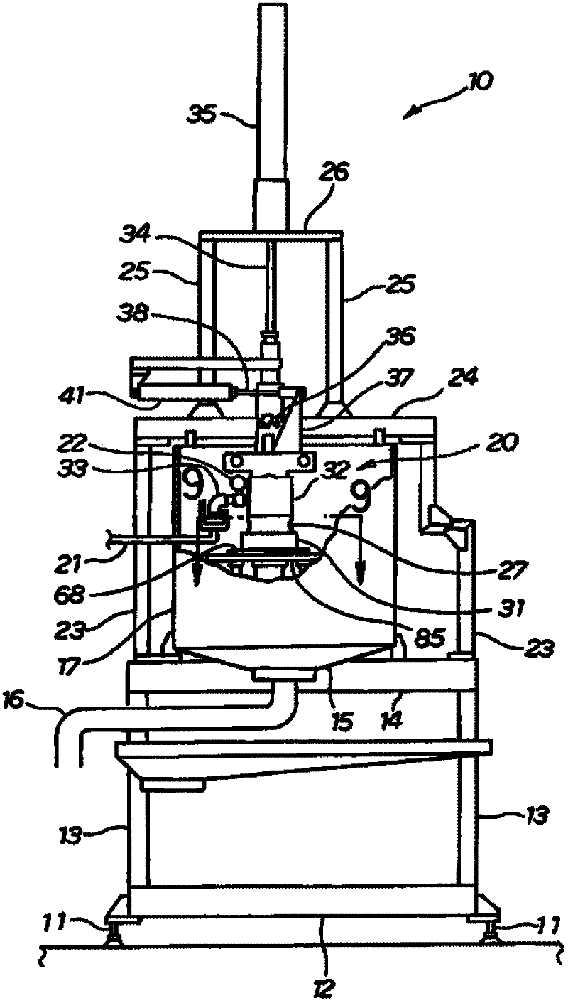
[0033] Such as figure 1 As shown, the cylinder surface treatment device 10 of this embodiment has: a base 12 with an adjustment device 11 , a lower column 13 erected from the base 12 , and an intermediate support member arranged at the upper end of the lower column 13 14. The tray 15 that is supported by the intermediate support member 14 and collects the treatment liquid, the treatment liquid discharge pipe 16 that discharges the treatment liquid collected in the tray 15 to the outside, and the cylinder member (囲い材材) 17 provided on the tray 15, The surface treatment part 20 provided on the intermediate part support member 14 so as to be surrounded by the cylindrical part 17, the drain pipe 21 provided on the surface treatment part 20 for guiding the drainage from the upper part of the surface treatment part 20, The treatment liquid detection part 22 which monitors the discharge of the liquid discharge pipe 21, the intermediate column 23 erected from the intermediate support ...


PUM


Abstract

Provided is a device for treating the inner surface of a cylinder barrel. A cover member (32) is provided, at the lower surface (59) thereof, with seal rings (54, 55, 56). The seal rings (54, 55, 56) are disposed concentrically about the center axis (63) of a cylinder barrel (43, 67). The lower ends of the seal rings (54, 55, 56) are disposed at different levels of height in such a manner that the farther away from the center axis (63), the higher the positions of the lower ends relative to the seal ring (54) closest to the center axis (63).

Description

technical field [0001] The present invention relates to a surface treatment technology of a cylinder provided on a cylinder body by bringing a treatment liquid into contact with the inner surface of the cylinder to treat the inner surface. Background technique [0002] Since the inner surface of the cylinder bore of the engine is exposed to high heat caused by the friction of the piston rings and the combustion of fuel, there is a demand for strength on the surface. In order to improve the surface strength, it is effective to perform surface treatment. In the case of performing plating treatment which is one of the surface treatments, it is required to remove dirt and the like on the surface in advance before the plating treatment. In this way, the treatment of removing dirt and the like prior to surface treatment is called pretreatment. exist Figure 11 An example of the pretreatment of the plating treatment is described in . [0003] Such as Figure 11 As shown, the pre...

Claims


Application Information

Patent Timeline
Patent Type & Authority Applications(China)
IPC IPC(8): C23C18/31C25D17/00
CPCF02F1/00C23C18/1619C25D7/04C25D17/004C23C18/1616C25D17/08C25D17/00F02F1/20C25D5/08C23C18/1803
Inventor 成瀬裕行唐泽均横尾健一
Owner HONDA MOTOR CO LTD
Why Eureka
Try Eureka