Electric machine with multiple cooling streams and cooling method

A technology of cooling flow and cooling slots, applied in the direction of cooling/ventilation devices, electrical components, electromechanical devices, etc.

Inactive Publication Date: 2011-11-30
SIEMENS AG
View PDF6 Cites 12 Cited by
  • Summary
  • Abstract
  • Description
  • Claims
  • Application Information

AI Technical Summary

Problems solved by technology

However, in order to ensure sufficient heat dissipation, traditional technology accepts this installation difficulty

Method used


Image

  • Electric machine with multiple cooling streams and cooling method
  • Electric machine with multiple cooling streams and cooling method

Examples


Embodiment Construction

[0014] The examples to be described in detail below are preferred implementations of the present invention.

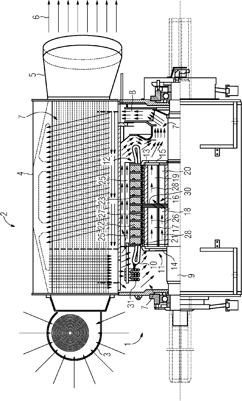
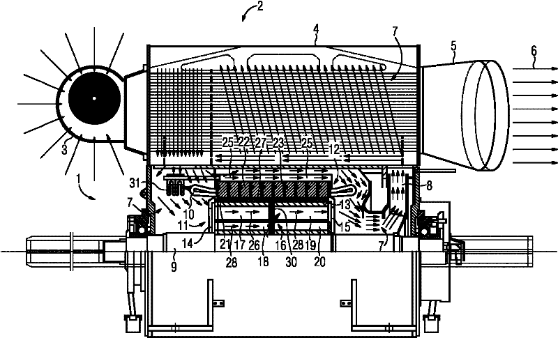
[0015] The drawing shows a generator 1 including a cooler 2 . The cooler 2 has a fan 3 to suck in cooling air and blow it into a heat exchanger 4 . The air in the heat exchanger flows to the outside through the exhaust pipe 5 . This forms an external cooling circuit.

[0016] The heat exchanger 4 cools the closed internal cooling circuit 7 via the external cooling circuit 6 . Driving the internal cooling circuit 7 is a shaft fan 8 mounted on the B side of the crankshaft 9 of the generator 1 . Starting from the fan 8 , the internal cooling circuit passes through the heat exchanger and enters the winding end region on the generator A side (drive side). The internal cooling circuit bypasses the winding heads 10 and the winding circuit 31 and passes through the rotor 11 and the stator 12, as will be described in detail below. Finally, the coolant (in particular air) p...


PUM


Abstract

The assembly of an electrical machine and, in particular, a permanent magnet generator is to be simplified without sacrificing cooling quality. Proposed for this purpose is an electrical machine with a stator (12), which has a winding support (22), which has at least one radial cooling slot (23), and a rotor (11), which likewise has at least one radial cooling slot (16). The winding support (22) of the stator (12) has on its outer shell a number of axially running cooling ribs (24), along which an axially running first cooling flow (25) can be directed.; Furthermore, the rotor (11) has axially running first cooling ducts (17), which open out into its at least one radial cooling slot (16), and so a second cooling flow (26) through the axial first cooling ducts (17) of the rotor (11), the at least one radial cooling slot (16) of the rotor (11), the air gap (27) between the rotor and the stator and the at least one radial cooling slot (23) can be directed in the axial direction along theaxial cooling ribs (24) of the stator. In this way, the stator can be cooled by two different cooling flows and, in particular, the number of radial cooling slots in the rotor (11) can be reduced, particularly to one, which simplifies production significantly.

Description

technical field [0001] The invention relates to an electrical machine comprising a stator having a laminated core with at least one radial ventilation slot, and a rotor also having at least one radial to the ventilation slots. The invention also relates to a method for cooling an electric machine of the above-mentioned type. Background technique [0002] In order to dissipate heat to the rotor and the stator of the motor, it is usually necessary to provide radially distributed cooling slots in both the rotor and the stator of the motor. In the case of so-called permanent magnet generators, if the rotor has a large number of radial ventilation slots, it becomes more difficult to install the permanent magnets in the corresponding slots on the rotor. However, in order to ensure a sufficient heat dissipation effect, the traditional technology accepts this installation difficulty. Therefore, the conventional permanent magnet generator has the same number of radial stator cooli...

Claims


Application Information

Patent Timeline
Patent Type & Authority Applications(China)
IPC IPC(8): H02K9/04H02K1/32H02K1/30H02K9/16H02K9/18
CPCH02K9/10
Inventor 奥利弗·梅明杰丹弗里德里克·舍贝尔诺贝特·舍恩鲍尔约翰·施特格纳罗伯特·丹纳于尔根·德拉贝丹尼尔·弗里德尔阿纳托利·福格尔
Owner SIEMENS AG
Why Eureka
Try Eureka