Catalytic cracking method and device

A catalytic cracking and catalyst technology, applied in the field of catalytic cracking, can solve the problems of many additional equipment and complex cooling measures for regenerants, and achieve the effects of increasing total liquid yield, improving product distribution, and reducing contact temperature

Active Publication Date: 2014-03-26
CHINA PETROCHEMICAL CORP +1
View PDF6 Cites 0 Cited by
  • Summary
  • Abstract
  • Description
  • Claims
  • Application Information

AI Technical Summary

Problems solved by technology

The disadvantage of this process is that although the residual activity of the gasoline spent catalyst is relatively high, there is still a certain gap compared with the regenerated catalyst.
This technology plans to add a regeneration inclined pipe and an air lift pipe, and set a catalyst cooler on the newly added regeneration inclined pipe. The cooled catalyst is mixed with the hot catalyst from the original regeneration inclined pipe, and the temperature is lower after mixing. The regenerant reacts with raw materials in contact. This technology can reduce the mixing temperature of the oil agent, increase the ratio of agent to oil, and improve product distribution. However, the cooling measures of the regenerant in this technology are slightly complicated and require more equipment.

Method used


Image

  • Catalytic cracking method and device

Examples


Embodiment 1

[0039] Embodiment 1 is comparative example

[0040] The test is carried out on a conventional riser catalytic cracking test device. The feed is pipeline transported mixed heavy oil. The main properties are listed in Table 1. The processing capacity is 30 kg / day. The activity was 62, and the carbon content was 0.05% by weight. The main operating conditions, product distribution and main properties of the products of the riser reactor are listed in Table 2 and Table 3.

[0041] Embodiment 2 comparative example

[0042] Press embodiment 1, difference is that feed is hydrogenated wax oil, and main character is listed in table 1, and processing capacity is 30 kilograms / day, and test used catalyzer is RSC-2006 industrial balancing agent, and the little reaction activity of balancing catalyzer is 60, with a carbon content of 0.06%. The main operating conditions, product distribution and main properties of the products of the riser reactor are listed in Table 2 and Table 3.

Embodiment 3

[0043] Embodiment 3 comparative example

[0044] According to embodiment 1, difference is that feed is hydrogenated heavy oil, and main character is listed in table 1, and processing capacity is 30 kilograms / day, and the catalyst used in test is MLC-500 industrial balancing agent, and the micro-reactive activity of equilibrium catalyst is 63, The carbon content is 0.03% by weight. The main operating conditions, product distribution and main properties of the products of the riser reactor are listed in Table 2 and Table 3.

Embodiment 4

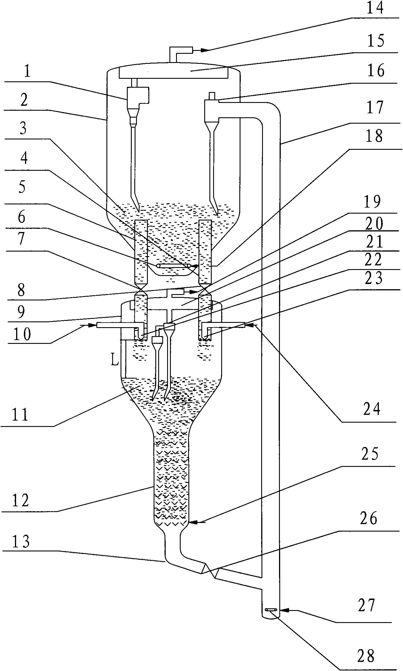
[0046] in such as figure 1 Test is carried out on the shown catalytic cracking test device of the present invention, and processing capacity is 30 kilograms / day, and feed, catalyzer are identical with embodiment 1, and the main operating conditions of riser reactor, product distribution and the main character of product are listed in the table 4 and Table 5.


PUM


Abstract

The invention discloses a catalytic cracking method and device, overcoming the defects of high gas and coke yields and low liquid yield which are caused by secondary cracking in the prior art. The method comprises the following steps: introducing a raw material oil into the lower part of a riser reactor so as to be contacted and reacted with a catalyst from a heat exchanger; carrying out crude separation on oil gas after reaction and a spent catalyst; further separating fine catalyst powder out of the reaction oil gas obtained by separation and then introducing the reaction oil gas without the fine catalyst powder into a fractionating column; carrying out steam stripping on the spent catalyst obtained by separation, and then introducing the spent catalyst subjected to steam stripping into a regenerator for regeneration; and introducing a part of regenerated high temperature reclaiming agent into the riser reactor from different heights of the riser reactor, introducing the other part of regenerated high temperature reclaiming agent into the heat exchanger, and the cooled reclaiming agent is recycled.

Description

technical field [0001] The invention belongs to the field of catalytic cracking of hydrocarbon oil in the absence of hydrogen, and in particular relates to a novel catalytic cracking method and device. Background technique [0002] In recent years, catalytic cracking technology has developed rapidly at home and abroad, and various new production technologies for increasing production of low-carbon olefins and clean gasoline have emerged one after another, but the maximization of economic benefits is always the goal pursued by enterprises, and low dry gas and coke yields, high liquid yield, It has always been the fundamental means for catalytic cracking technology to improve economic benefits. Various research institutions at home and abroad have made fruitful research in this area, and the developed technologies mainly include the following: [0003] UOP company's "X design" (US 5451313), UOP company invented this new design in 1995, its purpose is to improve the ratio of a...

Claims


Application Information

Patent Timeline
Patent Type & Authority Patents(China)
IPC IPC(8): C10G55/06
Inventor 闫鸿飞王龙延刘昱孟凡东张振千汤海涛王文柯陈曼桥张亚西
Owner CHINA PETROCHEMICAL CORP
Why Eureka
Try Eureka